Exporting usable CAD data from Maya

It’s that time of year again:  Time to help my father build a new aluminum boat.  It was an enjoyable process last year:  Based on a napkin sketch with some dimensions and angles he gave me, I modeled a boat out of NURBS in Maya, and through a lot of hoop-jumping, got him some useable data:

The biggest hurdle was getting him ‘the usable data’. The process of making the boat in Maya is discussed above.  But these were the export steps:

  • Export the mesh from Maya as obj.
  • Use online converter to go from obj -> pdf.
  • Then, my father gave the pdf to a buddy who traced it in CAD, gave it dimensions, then provided that to the plasma-cutter (as a DWG).
  • Ugh.

That process was super clunky.  I’ve been using Maya since… 1998(?) and never once needed to export anything CAD related, so this was all new territory.  To make this work I need a way to generate the CAD data myself, add dimensions to it, and export out as a DWG.  There must be a better way!

Turns out there is (and probably even a super-moar-better way than what I’m about to describe, if you know CAD better than I do, which wouldn’t be much of a stretch).  In the back of my head I remembered that Maya has a DXF exporter.  I don’t think I’ve ever once used it…

Part 1: Get CAD Software & Configure

Since this process is (currently) a once-a-year thing, I didn’t want to drop a bunch of cash (any really) to get some newfangled CAD software.  I’d read a lot about FreeCAD on the interwebs, it was available for Mac, so I installed it.

Fumbling around however, I realized it neither could import DXF, or export DWG, by default.

To get the DXF importer\exporter working, I followed the instructions here.

I never could actually get the DWG export working from the software, even following the instructions here.  However, that links to a standalone “Teigha File Converter” that will batch convert a directory of DXF files to DWG.  Good enough.

Also, this data needed to be in inches, so I changed the FreeCAD prefs as such.

Part 2: Export usable CAD data from Maya

I started by exporting the unrolled mesh as DXF from Maya:  There are zero options available.  But FreeCAD happily imported it.  Immediately, problems:  Missing triangles (you must exported triangulated mesh, can’t have quads\n-gons).  As a check, I exported this same data out as DXF, and reimported it:  Empty.  I don’t think FreeCAD likes to deal with polygonal mesh.

Next, I tried exporting the unrolled NURBS surfaces as DXF:  Those came in as empty groups in FreeCAD…

Finally, I converted the trimmed NURBS to their perimeter curves, and exported the curves:  Success!  This is what is important to know:

Export NURBS Curves from Maya as usable CAD data.

Polygonal Mesh = highly questionable.  NURBS Surfaces = no go.  Note I also tested locators & ‘distanceDimShape’ nodes:  They don’t export at all.

Once I had the boat’s unrolled\flattened curves in FreeCAD, I started adding draft dimensions.  Where I encountered my next problems:

  1. The scale was off by a factor of 10:  Even though Maya was set to inches, and FreeCAD was set to inches, everything was 10x as small in FreeCAD.  I noticed this is the same issue when I 3d print in cm:  Even though I have Maya in cm, and my slicer (Simplify3D) is in cm, they come in 10x smaller.  The fix?  Scale everything up in Maya 10x before export.
  2. From the top view in FreeCAD, all the curves looked just like Maya.  But when I went into a perspective view, the curves were actually going shooting up & down in space quite a bit:  Not on a flat plane.  But they are in a flat plane in Maya.  What’s going on?  Long story short:  In Maya after you do the 10x scale up, be sure to ‘freeze transformations’ on all the curves.  In addition to the scale, I had many other translate and rotate values on the curves to get them flat on the ground plate.  It appears that FreeCAD hates this.  But once everything was frozen, the curves showed up a-ok, from all angles.

Note:  Maya uses the Autodesk ‘DirectConnect’ file translators to export (and import) DXF data.  See the docs on the 2016 version in this pdf.

Part 3 : Add Draft Dimensions

Since I was told that this needed to be provided to the plasma cutter in inches, in FreeCAD’s ‘General -> Units’ prefs, I’d set them to “US customary (in/lb)”.  Next, via FreeCAD’s ‘Draft’ toolbox, I used the ‘Dimension’ tool to provide width & height values for all the curves.  This is where I ran into the next (and as of this authoring, unresolved) issue:  FreeCAD seems to auto-change the what unit is displayed in the dimension based on the length of the part being measured.  For example, I want all the dimensions to be in inches.  But they’d report inches, feet, and yards, depending on the length of the part.  After posting this issue to the forums, I learned that if you switch the units to “Imperial decimal (in\lb)” the dimensions will always be in inch.  Problem solved.  Thanks forum peoples!

Part 4 : Export

From FreeCAD, I export all the curves and dimensions as DXF, then using the Teigha File Converter, convert that to DWG.

And…. done?  Still need confirm from the plasma cutter the DWG is valid (I have no way of testing myself), but overall, a far less clunky data-export-pipeline than last time :)

Giving the C-Bot’s Octopus some glasses

I recently got OctoPrint working on my C-Bot.  It’s been pretty nice to remote-login and check my prints (and an emergency shutdown once during a jam).  One of the last remaining issues has been the quality of the timelapse video.

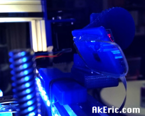
I’m using a Raspberry Pi camera module, and based on where I’ve mounted it (front top cross-member of the bot), plus the size of my build platform (12″ square), it prefers to focus on the rear of the platform, rather than the middle.  The effect is that anything from the middle to the front comes out blurry.

I’d read on the forums that you can use a pair of +2 reading glasses to pull that focal-distance closer, so I trekked to Walgreens today and picked up three pairs for $10 (It was 3 for the price of one):  I got these values to test: +1.25 (they were out of +1.5), +2, +2.5.

After popping them out of the frames, based on testing, it looks like the +2.5 increased the quality the best:  I was immediately able to see fine detail at the middle and front of the build platform.

But how to mount?  The pi_cam_head_v2.stl file sure wasn’t modeled to support reading glasses.  Hot glue to the rescue (aka, manual 3d printing) :

glasses

View is from the right-front corner of the build-platform, with the front leadscrew in-frame.

Making sure to first clean it really well, and center it on the camera itself, I simply ran a bead of hot-glue along the top and bottom edge of the lens, .

The only easy way to tell the difference is to compare the timelapse vid’s I’ve made to date:

  • First vid ever, low-res, low quality encoding, out of focusEiffel Tower

Only place to go from here is to mess with the encoding more, see if I can bring that quality up, and possibly get a fish-eye\wide-angle lens for it.

New 3D Print : Reindeer!

My wife asked me to print out a Reindeer for the holidays:  I found the “Holiday Christmas Deer” on Thingiverse, a great looking model.  Plus the shape of the model would take full advantage of the C-Bot’s build volume.  Print came out looking great.  And a new HD timelapse via Octoprint:

christmas_reindeer

You’ll notice at the 6 sec mark my hand go in for some “manual” supports 😉

Print Stats:

  • Model height:  20″
  • Print time: 9 hours
  • 2 shells, 8% “fast hexagon” infill.
  • 300 micron layer height
  • 6mm E3D-v6 Volcano nozzle
  • Sliced in Simplify3D
  • Printed at 90mm/sec
  • Gizmo Dorks blue PLA, extruded at 220 degrees.

New 3D Print : Eiffel Tower

I’d found a great model if the Eiffel Tower on Thingiverse:  I’d wanted to print it on my C-Bot for some time (since it seemed like a great way to maximize its build volume), but I knew with all the required retractions, the Bowden extruder would never handle it.  After recently switching to a direct-drive extruder, it seemed approachable again.  And with the recent attacks in Paris, I felt a desire to somehow pay my respects to that beautiful city, and landmark.

eiffel_tower

It didn’t go entirely smoothly though:  The extruder jammed when it hit first landing… I think all the super small handrails caused possible retraction issues, and the filament notched.  But I was able to reslice/reprint it right at that point, and glue the top on.  You’ll see this failure in the above movie… which was my first time making a timelapse in Octoprint, so the quality is a bit low as I figure out the settings.

The print looks fantastic, especially in the sun or with a light shining on it at night.  Really happy with the results.

Print stats:

  • Model height:  20″
  • Print time: 69 hours (yes, 69 hours)
  • 150 micron layer height
  • 6mm E3D-v6 Volcano nozzle
  • Sliced in Simplify3D
  • Just over a pound of material
  • Printed at 60mm/sec
  • Makergeeks white PLA, extruded at 230 degrees (per their recommendation)

Building the C-Bot 3D printer: Part 31 : Setting up Octoprint

Jump to C-Bot blog index to see all the posts.


My previous post talks about the specifics of getting Octoprint setup, in general.  Here, I’ll talk about actually integrating it with my C-Bot 3D printer.

Up to this point I had a Raspberry Pi (upgraded to a v2 at this point) connected to my router via a USB wifi dongle, with a RaspberryPi Camera hooked to it, connected via a 3′ ribbon cable.  This was all sitting like a pile of spaghetti on my table.  I needed a way to get all this strapped to the C-Bot itself, which is what this post mainly talks about.  I should comment that during this process I gave up on the USB wifi dongle and switched to direct ethernet:  Just too many problems getting the wifi to stream the picam correctly.

Before we get into it, the end result:

3D Printed Items:

I needed a way to mount both the RPi2 to the frame of the C-Bot, and have some sort of adjustable mount for the camera.  Both of the below items were printed on my Makerbot Replicator 1.

RPi2 case:  After searching Thingiverse, I found this great looking “Raspberry Pi 2/B+ case with VESA mounts and more” file:  It both looks slick, has a slot for the RPiCam ribbon cable, and had holes to bolt it directly into the OpenBuilds V-Slot.  I should note the holes provided were too small for the V-Slot bolts:  I had to drill them out slightly, but once that was done it was easily mounted (see above pic, it sits on the right-front vertical arm).

PiCam Mount:  After more Thingiverse searching, I tracked down “B+ PiCam Ultimaker 2 timelapse harness” : This is both an adjustable arm to hold the cam, and a separate bracket for the cam:  I printed out all the files needed for the cam, and realized that it didn’t fit the 20×40 V-Slot: The ‘hook front’ piece was too wide to clamp properly.  I’d figured this would be the case, and created a modified version in Maya to narrow it, which is currently installed on the bot.  But if you don’t want to have to deal with this, I realized you can get a pack of small sticky-notes, and just tear-off the appropriate amount to create an easy-sized shim.  You can download my modified version on Thingiverse here.

Assembly:

  • I bolted the RPi2 case to the right-front 20×40 V-Slot extrusion.
  • I attached the PiCam mount on the right side of the top-front x-extrusion.  Zip-tied it down for safety.
  • My Rumba’s USB now runs directly into the Raspberry Pi 2.

Issues:

  • RPiCam ribbon:  Not easy to route, easy to catch things on.
  • Power to the RPi, the way I mounted it sticks out the side of the bot.  Easy to catch things on.

Final thoughts:  I’ve literally just started printing with it:  I usually print from either the C-Bot’s LCD, or from Simplify3D : So this is a whole new interface to learn (although, obviously similar to what I’m used to).  But I’m excited to start nocking out some timelapse movies :)