Building the C-Bot 3D printer: Part 6 : Tapping the linear rail

Jump to C-Bot blog index to see all the posts.


Six of the aluminum OpenBuilds v-slot linear rails need tapped for their M5 bolts:  The four vertical legs, and what I’d describe as ‘the two top Y-axis beams’.  The legs only need tapped on one end, while the two other beams need tapped on both sides.

I borrowed my buddies M5x.8mm tap and got to work:  I’ve got to say, this has been the least enjoyable part of the whole operation to date:  16 holes  to tap (2-holes per end * 8 ends) fell into a rhythm:  Squeeze anti-seize paste into a hole, twist tap 21 times, untwist 21 times, meticulously remove shavings and paste from tap, clean paste from hole, screw in M5 bolt to test, repeat.

Gotchas:

  • Everything was cruising along fine until I got going too fast, twisted off-axis, and snapped the tap off in one of the holes.  Which stopped activities for the evening.  Luckily this was one of the legs that only needed tapped on one end:  I used my angle-grinder to shave off the remainder of the tap sticking from the hole, relived to know I could tap the other side.  Next day got a new tap from Home Depot and finished the job.  Lesson learned:  Go slooooooow….
tap_tap_tap

TAP!


Jump to C-Bot blog index to see all the posts.

Building the C-Bot 3D printer: Part 5 : Printing the parts

Jump to C-Bot blog index to see all the posts.


This is really ‘Part 0’, since Mason printed all these parts for me (on my Rep1 he was borrowing) while I was on vacation, before I even started blogging about it.  But it’s worth bringing up the specifics.

Carl Feniak has a full list of the stl’s to download & print over on the C-Bot’s OpenBuilds page.  Mason ended up 3d modeling the entire printer in Maya as a sanity-check for himself, and based on that, made some adjustment to Carl’s files (which my prints are based on).  If Mason posts those updates I’ll be sure to link to them.

I still need to print out a few more things, like the attachment for the E3D Volcano, but otherwise most of the printing is done.

Print settings were:

  • Printed on Makerbot Replicator 1
  • MakerGeeks ‘Maker Filament’ PLA 1.75mm, “Soulful Blue
  • 300 micron layer height, 2 shells (probably should have been 3), 40% infill, 4 ceiling/floors, .4mm nozzle
  • HPB @ 60 (to help them stick\lay flat)
  • Sliced in Simplify 3D
printed_parts

The filament is slightly translucent, and a really nice color blue.


Jump to C-Bot blog index to see all the posts.

Building the C-Bot 3D printer: Part 4 : Cutting the linear rail

Jump to C-Bot blog index to see all the posts.


While I really wanted to use this printer build as an excuse to get a chop-saw (and I could have done this on my table saw), the offer of my buddy Mason to go to his house and borrow his sounded pretty good too:  While I’ve used quite a few tools in my life, I’ve never actually used a chop-saw, and it’s always nice to do something with someone who has experiencing doing it themselves.  Not that chop-saws are rocket-science.  But after using one, I think I’ll add one to my Christmas list…

For my build, I ordered nine meters (in one meter sections) of the 20x40mm, which would get cut into 14 separate pieces.  I would have needed more but Mason had an extra length of it, plus the 20x60mm I need.  +2 more cuts…

I hauled all my OpenBuilds v-slot linear rail over to Mason’s and spent the next few hours marking them, and cutting them up (along with the two Acme lead screws).  Could have gone a lot faster, but we were in no hurry, and time was spent staring at his C-bot and dreaming of the future :)

Overall it went very smoothly, nothing outstanding to note.  After I brought them home I spent a good amount of time with a dental pick (they’re awesome) and steel file de-burring all the cut ends, and cleaning them up.  Next up will be tapping the ends for the metric bolts (part 6).


Jump to C-Bot blog index to see all the posts.

Building the C-Bot 3D printer: Part 3 : Power Supply Modification

Jump to C-Bot blog index to see all the posts.


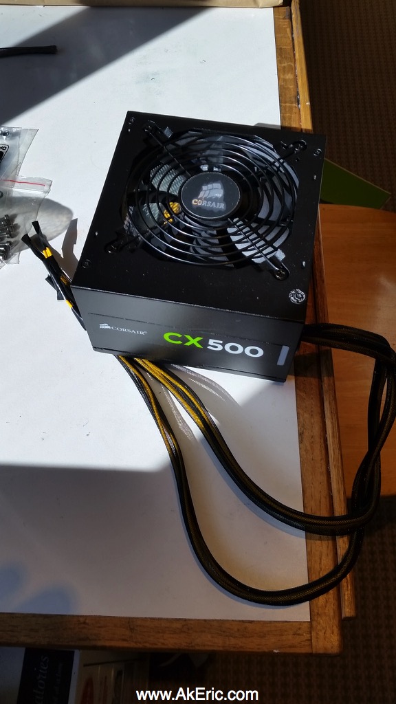
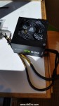
For this build, based on the recommendation of Mason, I picked up a Corsair CX 500 PC power supply from newegg.  500 watts of power, can do 38A at 12v (with a single dedicated 12v rail), so should be more than enough power for now, but room to grow.

Simple current calculations based on the biggest offenders:

  • 6x nema 17 steppers @ 1.68A (max) = 10.08A :
    • Core-XY mechanics, x2.  Z-stage. x2, Extruder, x1 (+ 1 extra for dual-strusion later…)
  • 12×12″ heated build plate : 20A
  • + other smaller draws.

After I got it he mentioned: “Oh yah, you’ll need to modify that too”.  Uh, what? :)

He pointed me to this great vid by MakerGeeks (I also like their (US made) filament), which shows you how to do the whole operation.

Highlights are:

  • Ground the green wire to trick the system into thinking there’s always a load.  Otherwise it won’t want to turn on…
  • Strip and plug the 12v wires/ground into your mainboard.

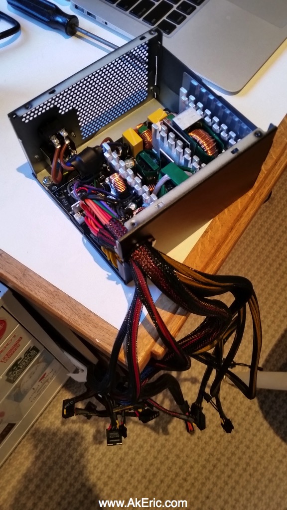
But this power supply has many bundles wires pouring out the side, far more than I’ll need.  I also knew this supply supported three different voltages, so after I hack-grounded the green wire using a paper-clip, I used my multimeter to check different colored wires:

  • Yellow : 12.46v
  • Red : 5.01v
  • Orange: 3.36v

Telling me, cut everything but yellow (and black).

So I got to work:  Opening the case, I isolated the green wire, and soldered it to one of  the grounds.  Heat-shrinked the result, tucked out of the way.

I need two separate lines of power out of the box:  One for the Rumba, and one for the HBP.  There were three bundles running out of the machine with yellow & black wires only:  Removing them from their protective mesh sleeving, I collected/connected (via twist & solder) three yellow/black for my HBP power, and another two yellow/black for the Rumba board power (could probably get away with one, I’m just playing it safe):  While the Rumba can power a HBP, it’s rated at 11A.  Since my monster 12×12″ HBP can draw up to 20A when heating, I need to connect it directly to the power supply (it’s temp will be controlled via a relay).  I choose to use three wires to visually match the gauge of the wires pre-soldered to the HBP.

Finally, everything else got chopped to about 3″ off the mainboard (in case for some reason I need to use them in the future).  I wrapped each end in electrical tape, wrapped the whole bundle in electrical tape, then clamped it down with zip-ties so nothing will come undone if things get hot.

I was very happy than upon reassemble it worked 😉  Next steps would be hooking it to the Rumba (which hasn’t arrived yet) and the heated bed.


Jump to C-Bot blog index to see all the posts.

Building the C-Bot 3D printer: Part 2 : Extruder Assembly

Jump to C-Bot blog index to see all the posts.


I chose a E3D-v6 Volcano as my printer head of choice:   Since the volume of my new printer will be so big, I need a nozzle that can keep up.  I’ve never used any of their products before, but have read many good things.  Purchased a ’12v, 1,75mm, Eruption – Full Hotend (Bowden)’ kit from Filastruder.  I should note they included surplus mounting hardware (washers, bolts, crimp-tubes, etc).  While I didn’t need them, I always appreciate the extras (including gummy-bears).

It happened to be one of the first things to show up, so that’s why it get’s blogged about first 😉

Links:

Notes on the build process:

The E3d-v6 Assembly Guide is well written:  I really only got hung up on the thermistor wiring:  When cutting and installing the ‘glass-fiber sleeving’, the ends constantly fray:  I found it quite difficult to get the thermistor + it’s sleeving shoved into the small hole on the heat-block successfully with the frayed ends: I had to enlist a sewing needle from my wife to aid shoving the ends in.  Later, installing the ferrule’s (crimp-tubing) proved even more difficult, since they wouldn’t want to slide over the frayed sleeving.  I persevered, but it was a huge time suck involving very tiny things my fingers didn’t like to grip.

The only other (very minor) issue was that the screws used to hold the cooling fan in were slightly too long: They’re sticking out a couple extra mm, I just couldn’t get them screwed in the whole way without stripping their heads.  If I get really OCD I may cut a bit off the end with my Dremel.

Overall, it took me around 2 hours, but I was really taking my time, and constantly getting up to get tools since I did it in my living room instead of my workshop, and was babysitting multiple prints going on my Rep1…

The final result:

e3d-v6_volcano  Beautiful!

Must remember to do the “Final Tightening” stage before my first print.


Jump to C-Bot blog index to see all the posts.