Portable Kinect scanning

protable_skanectI’d done a few experiments in the past with the Kinect / Skanect software (here, here).  The biggest issue (other than my underpowered Macbook Air) was that you’re tied via the USB cables to both the computer, and the electrical socket in the wall:  Hard to walk around things to scan them.

After looking at the wall-wart for the Kinect, I saw that it works off 12v DC:  Based on that, I picked up a small 12v Tysonic battery from Jameco, cut off the wall-wart, and soldered in some alligator clips to the power-cord.  Now the Kinect clips directly to the battery (which fits in my pocket), allowing me to hold the Kinect in one hand (based on this sweet 3d-printed grip), my laptop in the other, for completely untethered scanning.

So while it is still way more clunky than an iSense/iPad combo, that battery only cost me $15, and I got the Kinect used for $50:  A slightly lower price-point than a iSense/iPad purchase 😉

Making (real) aluminum boats in Maya

render_persp

Maya render of the boat

pops_bro_boat

Current state of the boat, with my father and brother.

My father has been building boats since before I was born and running them on the rivers of Alaska:  Fiberglass canoe?  Check.  Flat-bottom wooden riverboats with dual outboards?  Check.  Should I mention the hovercraft? 😉  Over the past decade he’s branched out into welded aluminum flat-bottom riverboats with great success:  Make one, use it for a few years, sell it and make an upgraded version.  (On a side note, I can’t wait to retire… <wink>)

Late last year he came to me wondering if I could help with the design:  Could I create the 2d design files he would provide to a local plasma-cutter to cut the main boat forms?  Sounded like a good challenge, and a great opportunity to collaborate with my father (He’s in AK, I’m in CA).  Up until then he’d get the huge sheets of aluminum and cut them by hand.  Having a plasma-shooting robot do that sounded like a more exciting (+ accurate/faster) solution.

My father provided me the drawn plans with angles and dimensions:  I started the process of turning those into real 3d forms.

Initially I attempted to do the whole project in Autodesk Fusion 360:  I’d been teaching it to myself, but I was still very much a noob in the software.  Unfortunately I just couldn’t get it to do what I wanted:  Most importantly I couldn’t ‘unroll’ the 3d forms to 2d forms, which is needed for plasma cutting.  I worked directly with their support on this, but the software just wasn’t quite there yet.

So I decided to do it all in Autodesk Maya (which I’ve been using since it was released in ’99).  While Maya is great for games\film\vfx, I’d never much considered it for accurate CAD-style modeling.  However, it ended up working great. Here are the main takeaways on how I built the boat:

The initial boat model:

  • I started by modeling the real-world size sheets of aluminum out of NURBS planes.
  • I snapped and rotated the pieces together to get the overall shape of the boat based on the provided angles.
  • I applied bend deformers on a single axis to shape the NURBS into the correct swept forms.
  • Based on all the intersecting NURBS, I created curve-on-surface intersections:
intersectingNurbs

Right side bent NURBS intersection, with curves-on-surface, before trim.

  • Based on those intersections, I trimmed away the excess aluminum (NURBS).
  • Boat model complete! (see above render)

The unwrapped form:

  • I needed to ‘unwrap’ all the bent surfaces back to flat planes for export.
  • To do this, I would duplicate each of the bent/trimmed NURBS, convert them to polygonal mesh, and wrap deform the polys back to the original bent NURBS.
  • On the original, I’d access the bend deformer, and zero it:  This would flatten out the wrapped polys.  I’d delete history on the polys, leaving it flat, then bend the original piece back.  I’d then scale it perfectly flat, since the wrap wasn’t 100% accurate.
  • I’d repeat that process on each bent piece, ultimately giving me unwrapped flat pieces for all parts of the boat:
unrolled

Unrolled polys

Exported 2d data:

  • I exported each polygonal mesh as obj.  I then used online software to convert the obj to pdf’s, which the plasma cutter could use.

After my father got the 2d data he printed a scale model on paper, affixed it to poster-board, and made a small-scale mockup as a sanity check:

paper_boat


From there, it was off to the plasma cutter…

And the most amazing part?  It all worked:  After my father got the pieces back from the plasma cutter and starting tacking them, they all fit perfectly.  Sighs of relief on all sides.

While it’s been fun to 3d print small items, it was super rewarding to see a much larger-scale 3d model become reality, and do some ‘real’ work with my father.  I can’t wait to ride in it!


Update:  See the final results here!

New Project: Adafruit Trinket NeoPixel LED Longboard

My son and I recently tackled the “Adafruit Trinket NeoPixel LED Longboard” project: Seemed like it would be a good cross between 3d-printing, electronics, and skateboards.  After running through it though, I found a number of problems with the instructions which I submitted here (if you’re going to do this project, be sure to read them).  Unfortunately at the time of this authoring they haven’t updated their project page to address the problems.

In a nutshell, this is what you need to look out for:

  • Need to order two Neopixel LED strips, not one.
  • There are problems with the wiring instructions, based on missing data.
  • Unless you have ninjaflex or nylon, you may want to entirely skip printing/assembling the front ring enclosures:  I printed mine in solid PLA, and they vibrated apart after the first ride (snapping the internal wiring in the process).
  • If you do print the rings, you really do need to use “wire wrap” to do all the wiring:  Larger gauge wire just won’t fit based on the printed models.  The problem I have with this is although you only need a small amount of wire wrap for the project, it’s best if everything is color coded, and buying wire-wrap in multiple colors actually gets a bit expensive.  I ended up using just two colors, and having to label all the wires (which pretty-much makes it impossible to fix if they snap after everything is assembled).

Overall it was a fun project, just seriously hindered by the confusing instructions, based on other issues I list in the above link.

Here’s the end result before the rings fell apart (and I removed them).  Note the metal bracket over the electronics enclosure and front of the  skateboard:  One jumped curb and you’ll have some smashed equipment without it.

Designing an extruder cooler for my Replicator 1

I purchased my Makerbot Replicator 1 nearly three years ago.  I don’t think at that point it was wide-spread knowledge that PLA likes to be cooled as it extrudes and  thus, no extruder cooler.  Most modern PLA printers have these standard.  Up until now, I’ve pointed a desk fan at my prints to provide cooling.

This weekend I decided to model up (in Maya) a fan mount to use as an extruder cooler:  Works great, uses the stock hardware so nothing new (other than the fan) is needed.  I use a removable glass build plate affixed with springy metal clips. These clips stick up off the build platform and will hit anything slightly lower than the gantry. Because of this, I designed this to shoot a jet of air just below the tip of the nozzle, but keeping the whole apparatus above the base of the gantry.

Download the model and get install directions over on Thingiverse.

[sketchfab id=”9e317b81ac7342dea61df0332dad8a28″]

3D Printer Surgery: Replacing my Makerbot Replicator 1’s Voltage Regulator

I purchased my Makerbot Replicator (1) when they were first released, nearly 3 years ago now.  Other than a few hiccups (HBP cable failing repeatedly, and a dead botstep needing replaced) it’s ran like a champ.  Reading the forums like I do, I’ve seen a number of people talk about their voltage regulators dying (the LM1084), and killing the whole board in the process.  I don’t know when I’m going to upgrade, and I’d like to keep this machine running as long as possible, so an update was in order.

Makerbot users are always a super-helpful bunch, and the folks over at the Makerbot Users Google Group are no exception.  I’d seen a lot of posts on the subject, but none that really broke down specifically what needed to be done, and what parts needed to be sourced.  So I asked, and they answered.  Armed with that knowledge (and this great photoset by JetGuy) I ordered from Digikey a “Recom Power R-78E5.0-0.5” voltage regulator (the 5v version, not 3.3v) based on user tramalot’s recommendation.  Below are the overall steps I took to install it.  It’s not hard once you grasp what needs done, and my hope is this breakdown can help others in the same situation.


First I sketched out the old and new wiring on paper:  The new regulator has a different pinout:  Everything has been shifted one pin left.

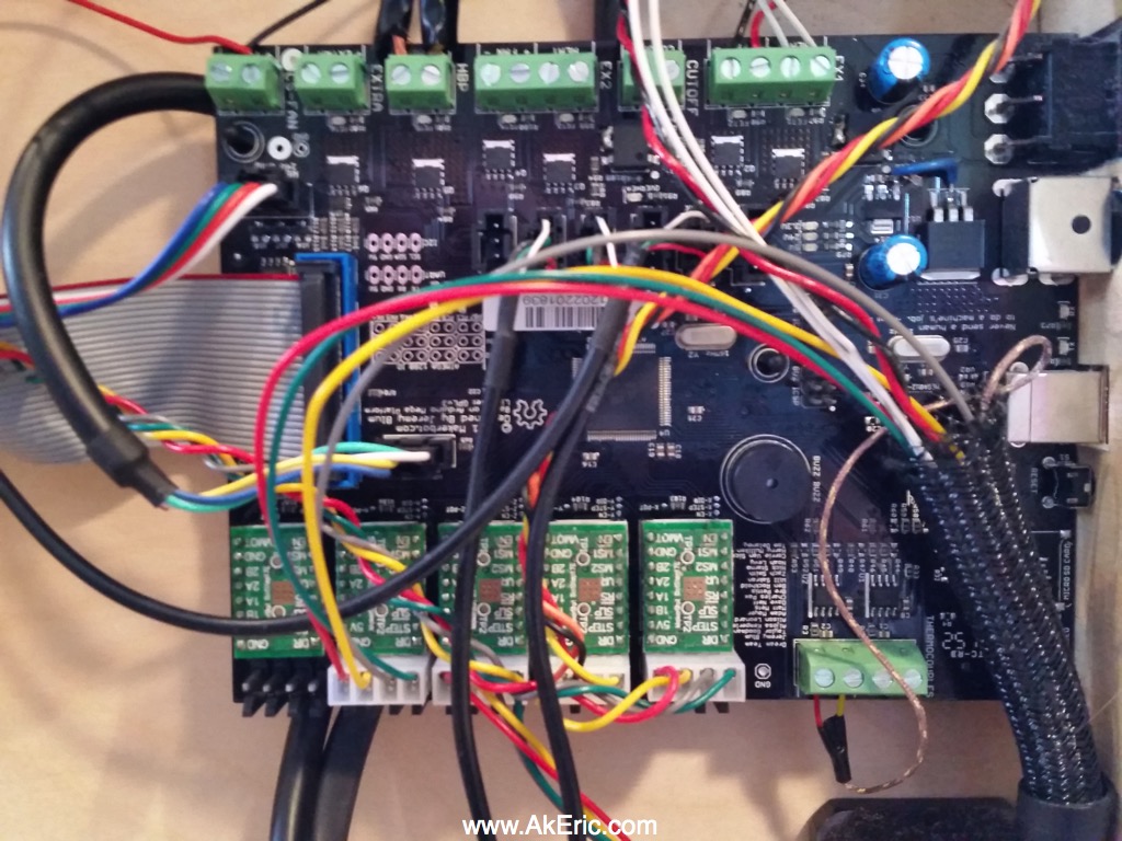
Next I snapped a pic of the Mightyboard pre-removal as a sanity check:

board_before

I made sure to ground myself with a wrist-strap just to be safe.

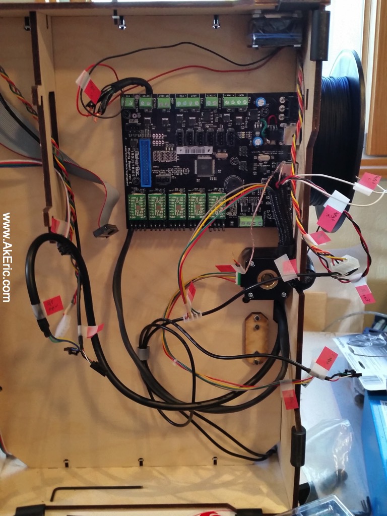
I then labeled all the wires with little stickies, unhooked everything…

spaghetti
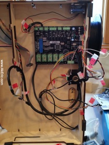
(note, this is actually the board on reinstall, but it’s all the same)

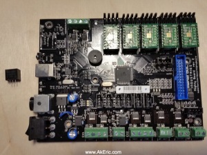
…and removed the board.  Here’s a shot of the bare board, and the new voltage regulator:

board_and_reg

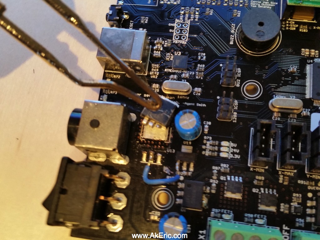
Like discussed in the forums, I used snips to cut the leads from the old voltage regulator.  I then took my soldering iron (the big, red, hand-held kind), and pressing it against the back of the reg, waited for it to desolder from the Mightyboard.  I lightly twisted the reg back and forth with a pair of pliers at the same time since I had no idea if just the pressure from the iron would move it.  It took a lot longer than I expected, and at one point I thought it wouldn’t work at all.  I’m guessing I had to hold it from 5+ minutes.

desolder

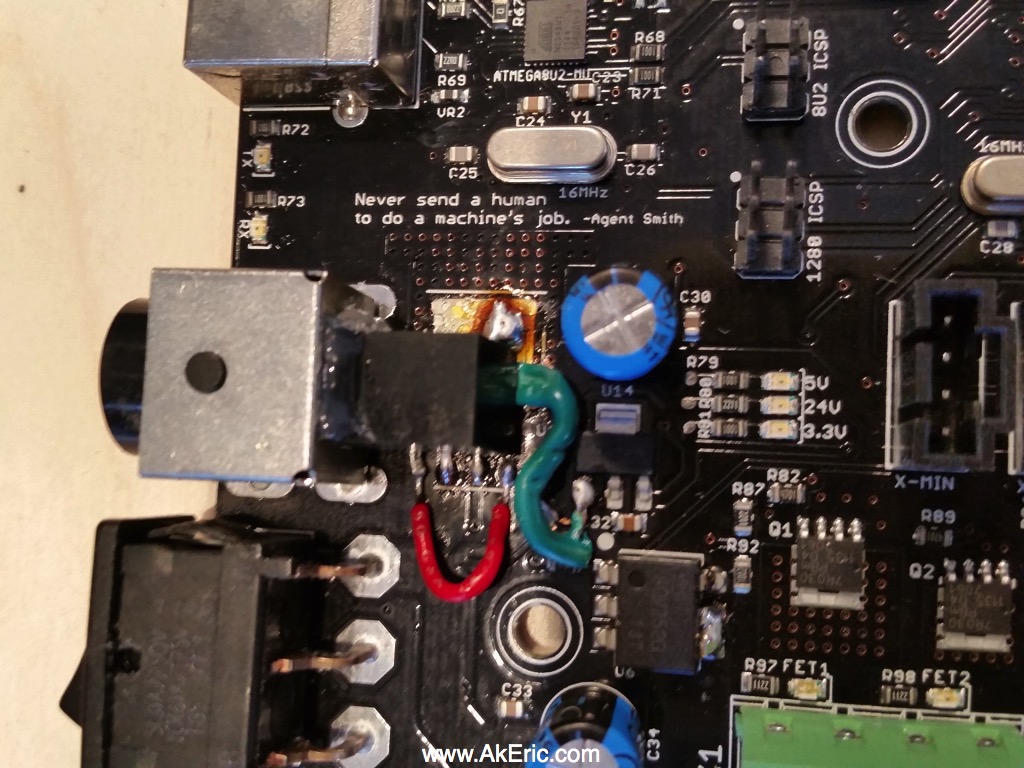
From there I desoldered the old remaining leads, and soldered in the new voltage regulator using wires to aid in the pintout offset.    I liked what JetGuy had done in his Flickr post, so I hot-glued it to the power receptacle for extra stability:

newInstall(Note the brown/orange cruft is just left-over flux)

Put it all back together, and I was relieved when it turned on, and printed successfully.

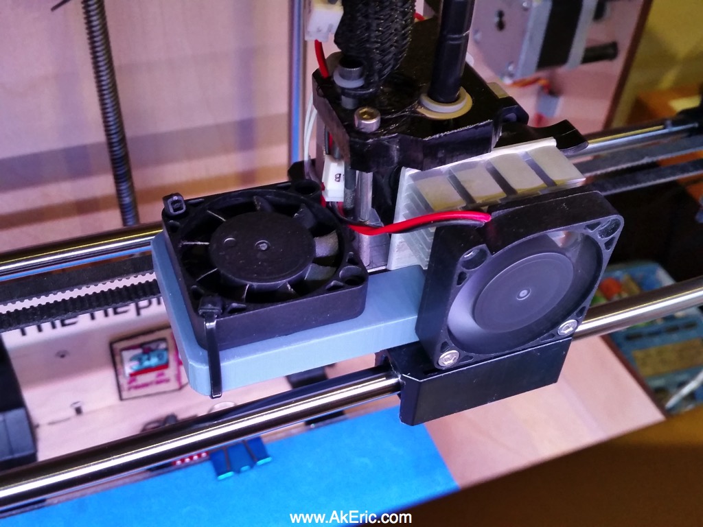
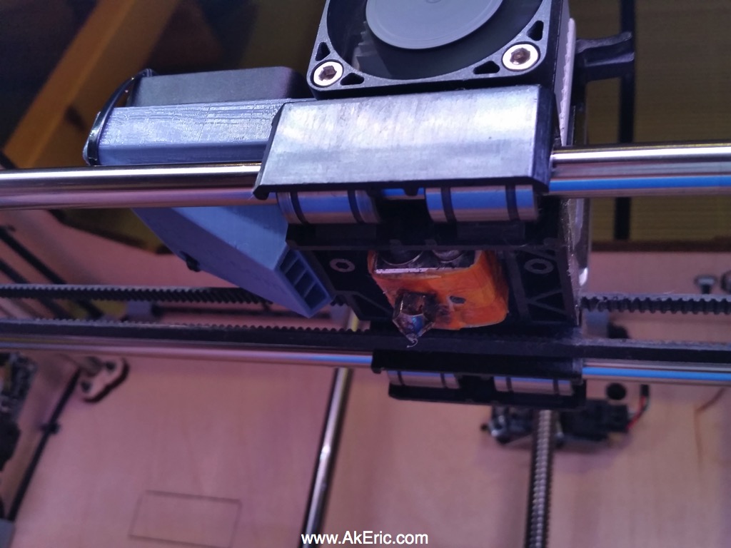
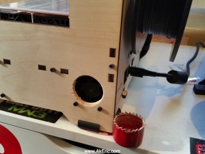
I figured while I had it apart I should provide for some extra cooling, so I drilled out a 1.5″ hole right by the Mightyboard fan.  However, after I did this I had more conversation on the above forum linked above, and learned that the Mightyboard really needs no fan cooling at all.  But… having it there should’t hurt.

newVent

Hope this gives my rep1 many more years of good printing :)

My thanks again goes out to the Makerbot Users Google Group users JetGuy, tramalot, and Joseph Chiu for their helpful advice!