Posts Tagged ‘ c-bot

Building the C-Bot 3d Printer : Part 33 : Machining a mic6 aluminum removable build plate

Jump to C-Bot blog index to see all the posts.


Overview

I’ve been using removable glass build plates for years on both my Makerbot Replicator 1, and my custom C-Bot:  I get double-thick glass cut at my local hardware store (Orchard Supply Hardware has had a great price on this), always thinking it was ‘totally flat’.  But is it really?  My C-Bot has a 12×12″ heated build platform.  When I go to level it with the glass, I get each of the four corners dialed in perfectly.  But the middle always sags slightly… even though it’s glass.  Double-thick glass.  But glass is actually somewhat plastic, and this sag has always bugged me.

Back in December I assembled my 1000mm X-Carve CNC, and it’s been so much fun cutting wood.  I knew it could do aluminum as well, but needed  a project.  And that’s what this post is all about:  Using my X-Carve to machine a new removable build plate out of .25″ mic6 aluminum for my 3d printer.  I am so happy with the results.

Sourcing the material

Before I started this, I had no idea what ‘mic6’ aluminum was.  It’s also referred to as ‘cast aluminum tooling plate’ or ‘ATP’, since mic6 appears to be a trademarked brand name.  Simplistically, it’s a standard for (among other things) a very flat aluminum plate, to .001″.  After reading a plethora of forms, and researching my local options, I settled on Midwest Steel And Aluminum’s “Cast Aluminum Tool & Jig Plate“, .25″ thick, 12×12”, which came to about $20, and the ground shipping another $20.  I could have bought it locally for $45 + tax (ugh).

A note on the order:  The plate was packaged in one layer of cardboard, that was it.  It appeared to have been dropped several times in-transit, 3 of the 4 corners were blunted, and there was an small indentation in the middle of plate itself.  If I was using this for something really precision I would have returned it.  Just a note to tell them to ship it better if you go this route.

Once it showed up, time to make some cuts!

Initial cuts

When I first got the plate I knew I had to notch a section out of each corner, since the heads of the bolts that hold the MakerFarm heated build platform stick up about 1/8″ish from it:  I didn’t want the plate resting on the bolt-heads, so I need to make little pockets for each.  Before I even considered my X-Carve CNC, I figured I could use my drill-press to pocket these.  Long story short:  It did not work well, and made a mess of the corners.  Based on that frustration I went down the ‘how about I use that dormant CNC right next to the drill press…” road.

For all below cuts, I used the same 1/8″ 2-flue upcut carbide endmill.

Since these cuts were so simple, I used Inventable’s Easel: I designed a circle with a diameter of .4″ across, .175″ deep, and used that to pocket each of the four corners already mangled by my drill press.  I used the default ‘aluminum’ Easel setting (5 ipm, .003″ doc, DeWalt on speed 1) with the first pocket (which took about 20 minutes), then started cranking it up: By the final pocket I had it running at 20 ipm at .01″ doc, with the DeWalt on speed 2, taking about 5 minutes..  It did great, and the bit was cool to the touch after the cuts.  When all four pockets were complete, it fit right on the bed with no collision with the bolt-heads:

cornerPocketAll the rough stuff to the right of the bolt-head was the abuse by the drill-press.

I have four bulldog clips that hold the plate on, one on the middle of each side.  The issue is even though I’ve bent them down to move them out of the way, parts of them still stick up slightly, and on a large print the nozzle could collide with them.  So going back to Easel, I designed a new rectangular pocket that would keep the bulldogs out of the way of the toolhead.  These were 2.25″ x .3″, cut .075″ deep.  I positioned them in the center of the left\right sides of the build plate, but had to offset them on the front\back based on my leadscrew config.

An in-process cut:

bottomPocketCut

And all four final cuts:

bottomPockets

Installed on the printer:  No more clearance problems with the bulldogs! :)

topBulldog

Prepping the plate

I use a highly secret (50% wood-glue, 50% water) slurry on my build plate to get PLA to stick.  But the mic6 is so smooth, I first scoured it with steel wool for several minutes to give the glue something to bite into.

Note for the future:  First, use something like lacquer thinner\acetone\mineral spirits to clean the plate of any oils:  Quite to my surprise, after many minutes of scrubbing, I could clearly see my handprint on it.  The oils deposited from my hand actually protected it from the steel wool.  So I went back and liberally scrubbed it with lacquer-thinner soaked rag, then went back to the steel-wool treatment again:  No more handprint.  Be sure to wipe it down with lacquer thinner after the steel wool too:  The wool actually leaves quite a bit of itself deposited into the aluminum.

After the plate was scrubbed, cleaned, and glue-slurry applied, I did some test prints.  And while the flatness was super awesome, I realized something very quickly:  The slicer said the bed heated up waaaay faster than it actually did:  For big prints in PLA, I’ll heat the bed up to 60c.

It dawned on me that the thermistor that does the temp reading is taped to the bottom of the MakerFarm heated build platform, while the thing being printed is sitting above it on .25″ of aluminum… that is taking much longer to heat up.

After brainstorming, I came up with the idea of cutting a groove into the bottom of the plate, that I could tape the thermistor into:  It should then be reading the temp from the removable plate itself, providing a much more accurate temperature.  This means I’ll also need to snip the leads running to the thermistor and install a barrel-jack into the mix to allow for the plate to be removed, since there’s now a sensor taped to it.

Secondary cut

Going back to Easel, I designed a .5″ wide groove cut .0312″ deep that I could recess the tape into, then another smaller groove .2″ across and .1″ deep to run the wires to the thermistor.

Here it is mid-cut:

bottomGrooveCut

Cut gotchas:

  • Easel has (based on what I’ve experienced) no idea of conventional cuts (bit spinning in the direction of travel) and climb cuts (bit spinning opposite direction of travel).  From what I’ve read, climb cuts can provide better finish, but only on ‘professional\beefy’ machines:  not the X-Carve.  Conventional cuts fare much better on the X-Carve.  This (as I found out) can cause dangerous problems.
  • When the top cut started, it was all conventional cuts, and cut fine.  But when the next layer started, and for every layer down, it was climb cuts.  Because of that, I noticed a lot of bit defection, chattering, and even gouging.  To avoid catastrophe, I had to manually monitor the cut, and really crank up the spindle speed as needed to compensate.
  • Note that MeshCAM gives you the option in the rough-cut to do either conventional or climb cut:  For future aluminum projects I’ll be using it for sure.

To help with heat transfer (that is only a theory of mine) and to prevent any sort of plate-slip (which is legit), I shoot the bottom of the plate with rubberized undercoating.  I then snipped my thermistor line, soldered barrel-jacks onto either side of it, then taped it into the groove on the bottom of the plate:

bottomFinal

Putting it back onto the HPB, I reconnected the barrel-jacks:

underWiring

Final thoughts

It works, great.

topFinal

When the HPB heats up, and it finally gets to temp…. it really feels like the top\bottom are the same temp.  And I can level each of the four corners, and the middle is the exact same distance as the rest of them from the toolhead.

Super rewarding project with one machine improving another.


Jump to C-Bot blog index to see all the posts.

Howto: Pause Repetier for filament reload at a specific layer number

Last year I posted Howto: Pause Marlin for filament reload at a specific layer number.  Since then I upgraded (I consider it an upgrade) to Repetier, and wanted to do the same thing.

The above link has a chunk of G and M codes  that could be inserted into the .gcode script at a given line number to pause it, allowing you to do a filament reload by hand. I figured you could do the same thing in Repetier.  As it turns out you can, and actually it’s a lot easier… presuming it works in the first place:

Repetier allows you to ‘Reload Filament’ via the LCD.  However, I immediately ran into a problem:  After the reload, it wouldn’t return to the correct position on the build plate:  It was always offset by some amount.  Basically ruining the print every time I tried.  Long story short:  You need to configure the firmware to “not home” after filament reload.  Two ways to do this:

Via the online configuration tool:  In the features tab under the “Filament Change” section, I set the “Homing after Filament Change” to “No Homing”.

Or in your Configuration.h set:

#define FILAMENTCHANGE_REHOME 0

Now, I can reload filament successfully via the LCD.

And via the M600 Mcode:  Up until then, whenever I’d try this code (which starts the filament reload process the LCD uses) I’d run into the exact same problem.  But now it works, so we can add it to our gcode file.

Why was this needed though?  You can follow the play-by-play on the Repetier firmware form here, but in a nutshell:  In my ‘start gcode’, I move my toolhead to the corner of my buildplate and ‘zero’ it there.  During Repetier’s ‘rehome’ operation during the reoload, it basically nukes those coordinates, thus putting an offset into my print.

Repetier’s ‘reload filament’ code is so simple (just that one line) compared to Marlin, you can easily enough by hand go into your gcode file, find the line number like this:

; layer 4, Z = 0.78

And insert it in where needed:

M600
; layer 4, Z = 0.78

Or, like mentioned in the previous post, you can use your slicer software (if it supports it) to post-process the gcode to add this in where you need.  Snip from last years post:

I slice using Simplify3D:  In a given process, it has a section in its ‘Scripts’ tab, at the bottom, called ‘Additional terminal commands for post processing’.  This allows you to enter in script to do a text-replace in your file, to edit it for you.  I learned about it on a forum post here.

To do the above using that system, you’d need to enter this text into that field:

{STRIP ";   postProcessing,"}
{REPLACE "; layer 4," "M600\n; layer 4,"}

And (like last years post),  some really important things to note:

  • The fist line that says ‘STRIP’ is super important:  If you don’t do this, Simplify3D will embed a copy of the REPLACE line in the header of the gcode, but won’t properly comment it out, basically ruining the gcode.
  • In the STRIP line, there needs to be exactly three spaces between the semicolon ‘;’ and the ‘postProcessing text.  Any more or less will screw up the strip.  If you copy-paste this code, make sure there are three spaces in there.
  • As you can see, you need to insert newline characters (\n) into the string you’re building for it to show up properly in the gcode later.

I have been made aware that you can also do something similar via Repetier Host:  The goal of this is to print entirely untethered, with precisely defined pause-points in the code for filament change, so host software (Repetier or otherwise) is out  of the question what what I’m trying to solve.

Building the C-Bot 3d Printer : Part 32 : New Cooling Fan shroud, and bulldog clips

Jump to C-Bot blog index to see all the posts.


New Cooling Fan Shroud:

Running PLA out of a volcano nozzle means you need a lot of cooling.  I’ve tried a number of solutions in the past, all of which were mainly just “point a really big fan at the hotend”.  I don’t think this is the best technique (although better than nothing) :  You want airflow directed at the filament immediately after it is extruded.

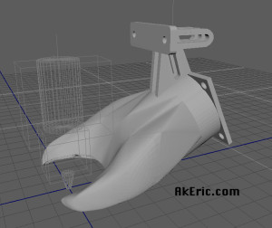
So I buckled down and designed a new cooling fan shroud in Autodesk Maya, specifically designed for the C-Bot, and the E3d-V6 Volcano nozzle I have attached to it.  You can download this file for print from Thingiverse here.  The most recent update allows you to adjust its mount location, hopefully allowing it to work with a greater variety of extruders on the C-Bot:

epfs_B03

Screenshot from Maya of B03

Here’s the previous version (B02) on my C-Bot:

cbot_filament_cooler

Low Profile Bulldog Clips

After installing the new shroud, it sits so close to the build platform, that it hits the side and rear bulldog clips I am using to secure the glass plate.  I looked all over the web for any sort of ‘low profile’ versions of these clips, but couldn’t find anything.

After a bit of thinking, I realized I could modify my existing clips instead:  Presuming you have two pairs of needle-nose pliers, a hammer, and a vice, you can do this too:

low_profile_bulldog New in front, old in back.

  • To get the clips out, jam one needle-nose into the hole of the clip, slightly opening it.  Use the other one to pull out each of the tabs.
  • Put the tabs together in a vice (with the lips of the tab in the vice), and pound it with the hammer over until they’re both 45 deg or more.
  • Slide one tab back into the clip.  Holding the clip with a needle-nose, work the other one in.  That’s it.

Next up, install on your removable bed.


Jump to C-Bot blog index to see all the posts.

New 3D Print: Maui

I’ve 3d printed a few other maps, and got a lot of enjoyment out of it:

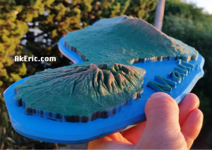
I recently spent a week in Maui:  This gave me inspiration to do a (painted) 3d print of it on my C-Bot:

maui_painted_main

The below post is an overview of how I designed, printed, and painted it.


Getting the Mesh Data

I first headed to the web app Terrain2STL : This is the great little program that lets you download 3d-printable terrain data.

However, no matter what you set the capture-box size to, it captures the same resolution of data.  If you make the box the size of the whole island of Maui, you end up with a pretty low-resolution capture mesh, based on the detail I want to 3d print.  So the only way to get a ‘high-res’ Maui mesh is to download many small chunks, that will later be seamed together to build a high-res island.

In Terrain2STL, I set the box size (ARC seconds) to 360.  Based on that size, I can adjust the latitude & longitude values by .1 values, to offset the box by one length in either direction.  So stating at the NW corner of Maui, I started capturing squares of it’s mesh.  In total, I made 30 captures.

Assembling the Mesh Data

In Autodesk Maya, I created a new scene, and started importing in each STL that Terrain2STL generated.  Starting in the NW corner, I’d import in the next stl, line it up with the last, and repeat that process.  Which gave me something that looked like this upon completion:

maui_maya_chunks_raw

I then went through the process of deleting all the mesh that wasn’t part of the island, stretching all the edges down to make a cliff-like effect, making a base for it, and creating the text.  I also did a lot of mesh cleanup since the Terrain2STL tool isn’t perfect.  Final Maya result:

maui_maya_final

tried to boolean all the mesh together, but Maya just wouldn’t do it.  This left me frustrated, but I realized that Simplify3D (the slicer I use) allows you to import in multiple mesh:  In Maya, I made sure the pivots of all the mesh were at the origin (so they’d all show up in Simplify3D in the correct location), the transformations frozen, and I exported every individual piece as a new STL.

Slicing The Data

I imported all the stl’s into Simplify3D:  They appeared to all line up correctly.  I wanted the island to be scaled 2x on the Z axis, so I grouped all that mesh, and applied the scale transformation.

But when I sliced it, I noticed lots of little gaps between the mesh chunks:

maui_sliced

Come to find out, even though all the mesh was lined up correctly, in some cases… it just wasn’t enough for Simplify3D : This spawned a painful process of me moving pieces, re-slicing, checking gaps, etc.  But eventually I got rid of them all.  The general prints stats were:

  • 200 micron, .4mm E3D-v6 Volcano nozzle
  • Maker Geeks Gray’matter Gray PLA @ @210 deg.  Bed @ 50 deg.
  • 90 mm\sec print speed.
  • 2 shells, 4 roof\floor. 10% ‘fast hexagonal’ infill.

Took around 13 hours to complete.  Based on my 12″x12″ build platform, printed diagonally it came out to 14″ across:

maui_noPaint

Painting the model

I wanted to try a new (for me) dry-brush technique to show off the mountains.

To start, I shot the whole model in a pleasing Rust-Oleum ‘Meadow Green’ color:

maui_midPaint

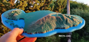
After that dried, I sprayed “Maui Blue” (can’t believe I found a color that matches the medium I’m painting) onto a foam brush, and painted up the ocean.  Finally, I sprayed a light-brown onto a paper towel, and then brushed it across the mountain peaks for the final result.

maui_painted_NW maui_painted_SW

Was really pleased with the results!

Tuning jerk values in Repetier

(Note:  Based on continual feedback I’ve been rewording sections, to hopefully make it clearer)

Now that I’ve switched my C-Bot over to new electronics (RADDS) and firmware (Repetier), it’s time to start getting serious about tuning:  After running some initial test prints, I wasn’t satisfied with the ghosting/ringing that was occurring on the prints, so I decided to tweak the Repetier jerk settings, since I know they can have an impact.

The goal of this test:  Really, to compare how jerk impacts print quality, and print speed (the value you set in our slicer) vs print time (how long the print actually takes).  I’m not making any recommendations based on these results:  You can make your own decisions based on the data presented below, and how that may impact your printer based on it’s mechanics & firmware.


I adjusted the jerk on the fly from the LCD, storing them back to EEPROM before each print.  The default jerk values in Repetier are 20, and can also be set via the ‘Mechanics’ tab via the online configuration tool (requiring a re-flash of the firmware from the Arduino IDE).  There is also a nice description of Jerk via the Repetier Firmware Installation Page.  From that page though, the high-level important stuff:

You want high jerk values, because

  • Printing time is reduced.
  • Print shows less blobs.

You want low jerk values, because

  • It causes less mechanical stress to your printer.
  • Moves are smoother.
  • Filament has better adhesion at directional changes.
  • Reduces printer noise.
  • You loose steps with higher values.

Other Hardware\Slicer Stats:

  • Hardware is RADDS\Arduino Due (32-bit ARM).  Stepper drivers are SD6128’s, at 1/32 microstepping, turned to .55v
  • The C-Bot is core-xy kinematics.
  • I sliced these in Simplify3D:
    • 2 shells, 4 roof\floors, 10% ‘fast hexagonal’ infill.
    • Outline underspeed at 75%:  I didn’t realize this until after the test (since it’s sort of standard operating procedure for better quality), but in hindsight I wish I’d turned it off for this test.
    • 200 micron layer heights.
  • .4mm nozzle on an E3D-v6 Volcano.
  • Print speed adjustment for cooling is disabled (no slowing down for small layers):   I didn’t want the print times to be adjusted because of print cooling.  However, the filament cooling fan is enabled (since I’m printing in PLA).
  • Used MakerGeeks Gray’Matter Gray PLA, printed @ 210 deg (they recommended 230 on the spool, but it seemed unnecessary).
  • In Repetier, my xy acceleration values are 1000 (default).

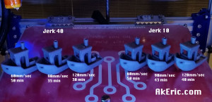
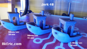
I printed two sets of three #3DBenchy models:  I chose the benchy since it’s small, but complex.  The first set was with a jerk of 10, the second with a jerk of 40.  For each set of three, printed them with these speeds:  60/90/120 mm/sec.  Below are a list of the times it took to print each.

Stopwatch was started when extrusion began, after nozzle & bed warmup.  Stopwatch was stopped when print completed, and end gcode ran.

Print speed/time comparisons, sorted by jerk:

  • JERK 10 | 60mm/sec:50min | 90mm/sec:43min | 120mm/sec:40min
  • JERK 40 | 60mm/sec:50min | 90mm/sec:35min | 120mm/sec:30min

compare_all(click all images for bigger pics)

What does this tell us about speed/jerk tradeoffs?


Numeric comparison of print time:

Based on the above speeds (mm/sec) and print time (in min) from above.

Comparing JERK 10 to itself:

  • 90mm/sec had a print time 1.16x faster than 60mm/sec, even though the speed was set 1.5x faster.
  • 120mm/sec had a print time 1.075x faster than 90mm/sec, even though the speed was set 1.33x faster.
  • 120mm/sec had a print time 1.25x faster than 60mm/sec, even though the speed was set 2x  faster.

Comparing JERK 40 to itself

  • 90mm/sec had a print time 1.43x faster than 60mm/sec, even though the speed was set 1.5x faster.
  • 120mm/sec had a print time 1.17x faster than 90mm/sec, even though the speed was set 1.33x faster.
  • 120mm/sec had a print time 1.66x faster than 60mm/sec, even though the speed was set 2x faster.

Comparing JERK 10 to JERK 40:

  • 60mm/sec jerk 40 had the exact same print time as jerk 10.
  • 90mm/sec jerk 40 had a print time 1.23x faster than jerk 10.
  • 120mm/sec jerk 40 had a print time 1.33x faster than jerk 10.

Things observed from the numbers:

  • There is not a linear relation in increasing the ‘speed‘ in mm/sec and reduction in print times (which I knew, but it’s nice to see real data back this up).  Meaning, if 50mm/sec took 50 min to print, 100mm/sec won’t take 25min, it will be some value in-between (based on factors like jerk, acceleration).
  • Interesting that 60mm/sec speed had the exact same print times for jerk 10 & 40 :  Guess at that speed the jerk-clamping has a lower effect.
  • There is definitely a point of diminishing returns on high print speed and low jerk.  At a certain point the low jerk clamps the speed so much that it can never accelerate high enough to have an appreciable effect on print time (this is my theory at least).
  • The larger (40) jerk value had the widest range in print time variance (30 min -> 50 min) since (I presume) the jerk wasn’t clamping down the speed so much.

Visual comparison of quality:

Comparing Jerk 10 to itself:

compare_jerk10

Across the board all speeds of jerk 10 did well quality-wise.  Nearly no ringing at 60mm/sec, and minimal ringing on the 90 & 120mm/sec.   The only really visual differences is the discoloration of the PLA as it was printed faster.

Comparing Jerk 40 to itself:

compare_jerk40

Ringing across all speeds.  Passable at 60mm/sec, but I don’t like what I see at 90 & 120.

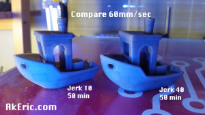
Compare 60mm/sec:

compare_60mmSec

While both had the exact same print time, there is virtually no ringing on the jerk 10, while ringing is visible on the jerk 40.  A strange random print artifact showed up on the smokestack of the jerk 10 that didn’t show up on any other prints.  Ghost in the machine.

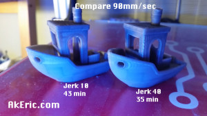
Compare 90mm/sec:

compare_90mmSec

Very slight ringing on the jerk 10, ringing is quite apparent on the jerk 40.

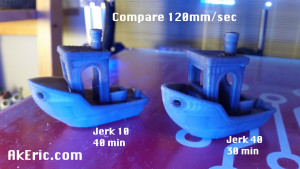
Compare 120mm/sec:

compare_120mmSec

Ringing is just starting to show on the jerk 10, and jerk 40 looks like a train-wreck.  Or a ship-wreck.

Final Thoughts, Opinions:

  • The default jerk values in Repetier are 20, which is why I wanted to try two values on either side that would really show off the differences, since I was still getting rigging at 20 at 90mm/sec before this test.
  • I think that you need to make a decision when starting the print:  Quality vs speed?  All depends on what you’re printing.  If this is a structural part where the visual artifacts of ringing are tolerable, then crank up that jerk.  But if it’s a artistic piece, then lower it down.  What’s nice is that you can adjust this from the LCD in Repetier and set it in EEPROM per-print, not requiring any type of re-slicing.
  • Maybe I’ll just set it back to 20.  HA!