Getting started with Adafruit’s Circuit Playground Express
Overview
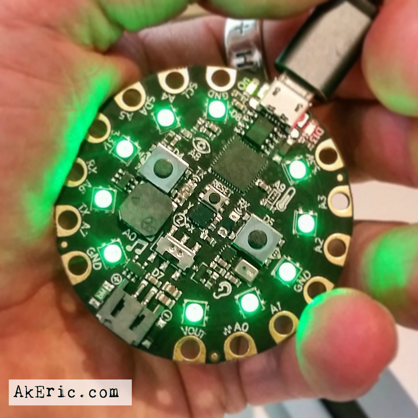
I’ve had a dream of authoring Python code directly on a microcontroller board for a long time. That became a reality with MicroPython and the pyboard, but I didn’t jump in until my Circuit Playground Express (CPE, below) board from Adafruit showed up recently.
 <- CPE in bootloader mode!
This blog post is written as notes for my future-self, when I forget things. But feel free to follow along reader…
I wrote this guide because despite the fact Adafruit has lot of data out there, it took me hours to sort through it all and figure out what applied, and what didn’t.
Circuit Playground Express Links
- Main Adafruit Sales Page
- Adafruit “Guides” for it can be found here.
- CAD file for the CPE can be found here.
- 3d Printable case by Adafruit.
Required Hardware
- Adafruit Circuit Playground Express
- Do not confuse this with the “Circuit Playground Classic“: It is a different thing (only supports Arduino).
- Micro-USB cable, capable of carrying data (not just charging). I got a 3-pack from Amazon that work well.
- A Computer. All my work was done on a Windows 10 PC.
Adafruit Setup Docs
It should be noted that I myself did all of these steps in the below order. Which makes me wonder, for example, if the drivers & utils I installed during the Arduino section benefited later steps. Each of these docs is broken out into more detail below The Bootloader section.
- Circuit Playground Lesson #0 : Arduino Setup
- This is authored for the “Circuit Playground” (the precursor to the CPE, it is a different thing), but docs still appears to apply. Probably the best first place to start, but focused on Arduino.
- MakeCode
- If you want to try your hand at MakeCode programming on the CPE (Visual blocks, or JavaScript), start here.
- CircuitPython Setup
- This is actually a sub-doc for another tutorial, but explains how to setup CircuitPython on the CPE.
- CircuitPyhon is based on MicroPython, with some differences.
The Bootloader
This CPE bootloader info applies to Arduino, MakeCode, and CircuitPython, so it’s worth calling out here.
- Nice (MakeCode) overview here: “Downloading and Flashing“. It should be noted that Arduino uploads via its own IDE, but you still need a bootloader to receive the data. More info under “UF2 Bootloader Details“.
- The first time you plug the CPE in over USB (before any other configuration / software installs), see if the bootloader works. Press the reset button twice: All the ring-LEDs should turn green, and D13 should be slowly pulsing. The image a the top of this post shows this.
- The issue I had is, the image in the linked docs don’t show the green LEDs: Since mine were green, and the image of the docs were not, I thought I had a problem. I did not.
- IMPORTANT: Once the software is configured correctly (this started happening for me once I configured Arduino), entering bootloader mode should pop open a (Windows) Explorer. However, the CPE has two different “Windows Explorer modes”:
- “Bootloader Mode” : Again, all the LEDs should be red, and you should see a few files on it:
- INDEX.HTM <- web link to the CPE
- INFO_UF2.TXT <- tells you about the bootloader
- CURRENT.UF2 <- the current firware
- “Program Mode” (I made that term up) : This is the the mode where you can drag & drop your programs onto the board. This shows up on first time plug-in (usually takes 30 seconds or so for the Explorer window to pop open), or when you press the reset button once. For example, with CircuitPython installed, I see these files:
- /lib <- imported bundle libraries
- code.py <- Main code to execute
- boot_out.txt
- “Bootloader Mode” : Again, all the LEDs should be red, and you should see a few files on it:
- Here’s a short video showing how the bootloader works:
Initial Arduino Setup
Based on Circuit Playground Lesson #0 : The links below are entirely from this tutorial, I’m just calling out some of the major points & gotchas.
I got the CPE with the goal of authoring Python code for it. But based on all the initial documentation I could find, it seemed like Arduino was where one should start.
Install
- From the docs for your OS: (Windows links below)
- Download Arduino IDE Software & install.
- Get the Circuit Playground Drivers & install.
- Add Circuit Playground to Arduino
- (Obviously) follow all the steps here adding drivers and external packages.
- This part really confused me for a bit (and Adafruit tech support to the rescue): Be sure to choose the right board from Tools -> Board Menu.
- The right board will be under the “Arduino SAMD (…) Boards” section, called “Arduino Circuit Playground Express”. Any other board with a similar name (like, say, “Circuit Playground”) is wrong. You’ll know it’s wrong because it won’t upload your sketch correctly.
- See verbose errors and whatnot from my forum post here.
- Once you’ve selected the correct COM port, you can then access:
- Files -> Examples -> Adafruit CircuitPlayground -> And choose a sketch therein for upload & test.
- Other Notes:
- During this process, I couldn’t get Arduino to connect. After rebooting my machine and restarting the Arduino IDE, it asked me to install additional drivers, which I did. Around that time things started working correctly.
Docs
- The Arduino “Adafruit Circuit Playground Library Reference” can be found here.
Initial MakeCode Setup
Based on Adafruit’s MakeCode docs: MakeCode provide a visual programming environment, JavaScript, all programmed in-browser.
Install
There really isn’t an “Install” per-say: Just browse to : https://makecode.adafruit.com to open the editor.
You can now code in either the “visual blocks”, or JavaScript.
Presuming you can enter “bootloader” mode (discussed in the Arduino section above), once you save a .uf2 file from the MakeCode app, if you drag & drop it onto that open Explorer window, the window should close, and the app immediately run on your CPE. Pretty slick!
I presume though, that some of those Arduino install steps were required, since my PC wouldn’t recognize the CPE as a USB device properly until then, which would have prevented me from dragging & dropping the .uf2 files onto it.
Docs
Initial CircuitPython Setup
From the Adafruit “Circuit Python Setup” docs (for the Metro M0 Express board, not that it matters so much).
This is the whole reason I got this hardware, so far, not disappointed!
Install
- The above docs do a great job of covering it, but be sure you choose “Circuit Playground Express” options, since the tutorial was written for another board.
- I flashed the CPE by just drag&dropping the downloaded ‘adafruit-circuitpython-circuitplayground_express-1.0.0.uf2’ (for CircuitPython 1.0, not 2.0, which at the time of this writing just came out and is in beta) file onto the CPE while in bootloader mode. Note, it did take ‘a while’ for it to update, at one point I thought maybe it had broken. But then it started working again.
- I used the CircuitPython Blinky example to upload my first Python module, and it worked!
- It appears that my current version of CircuitPython is running Python version 3.4.0.
Getting Bundles
- CircuitPython ‘bundles’ Python libraries together for use on the CPE. Since the space on the CPE is so limited, sometimes you can only include specific compiled libraries with your module.
- You can access the bundles here @ github: adafruit/adafruit_CircuitPython_Bundle
- Don’t make the mistake I did: Just grab (for example) the “adafruit-circuitpython-bundle-1.0.0-20170815.zip” file in the downloads section, not one of the individual libraries above: They don’t have the ‘lib’ folder you need for transfer to the CPE.
Setting up a Serial REPL Editor
This is a great feature, that allows you to have a live Python interpreter running on the CPE. This lets you query the board directly in a live coding session, awesome feature. What is REPL you ask: Answer here!
An overview of how to set this process can be found here: “Serial REPL“.
Other Info:
- I used PuTTY for this connection.
- It looks like the COM port for my CPE changes pretty often, so I have to access the Windows Device Manager every time I want to run this feature. Mine shows up as “Teensy USB Serial”, and tends to bounce around COM9->11
- You can’t connect when you’re in bootloader mode: Get a program running first.
- Note, on first time connect, you can’t connect in via REPL until the Windows Explorer (auto) opens: That signifies that the machine is ready.
- If, when the terminal screen comes up its black/no info, hit ctrl+c to break out of the running program and access the terminal: >>>
- type help() to see a list of built-in functions.
- You can use this same connection (before the ctrl+c) to see the output of any module currently running.
Docs
- Adafruit Circuit Python API Reference
- CircuitPyhon Github source.
- Example code can be found on Github here.
- CircuitPython is based on MicroPython: What is MicroPython?
- Adafruit CircuitPython Guides.
- Adafruit MicroPython Guides.
Really look forward to seeing what this little board can do!