Posts Tagged ‘ c-bot

Building the C-Bot 3D printer: Part 21 : Software Day 4: PID Autotune & start/end G-Code

Jump to C-Bot blog index to see all the posts.


Total time : 2.5 hours

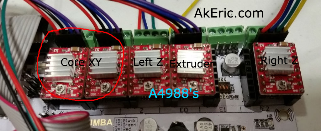
Even though I need to really un-spaghetti the machine and do the final wiring, I can’t help but want to print more, especially since I installed & tuned the DRV8825 stepper drivers:  I want to make sure they actually work!

Start & End G-Code

At the same time, I wanted to create better start & end G-Code for the bot:  I slice & print using Simplify 3D (S3D):  When you create a new custom printer profile, for the start G-Code, all it does is a G28:  Auto-home.  It seems to take care of the extruder and bed heating for you.

In addition, even though I’d previously figured out how in S3D you can set ‘global G-Code offsets’ in its G-Code tab, which lets you define the offset between home and the build platform, I thought it’d be better to set it in the start G-Code instead. I don’t know why, but it feels safer in there…

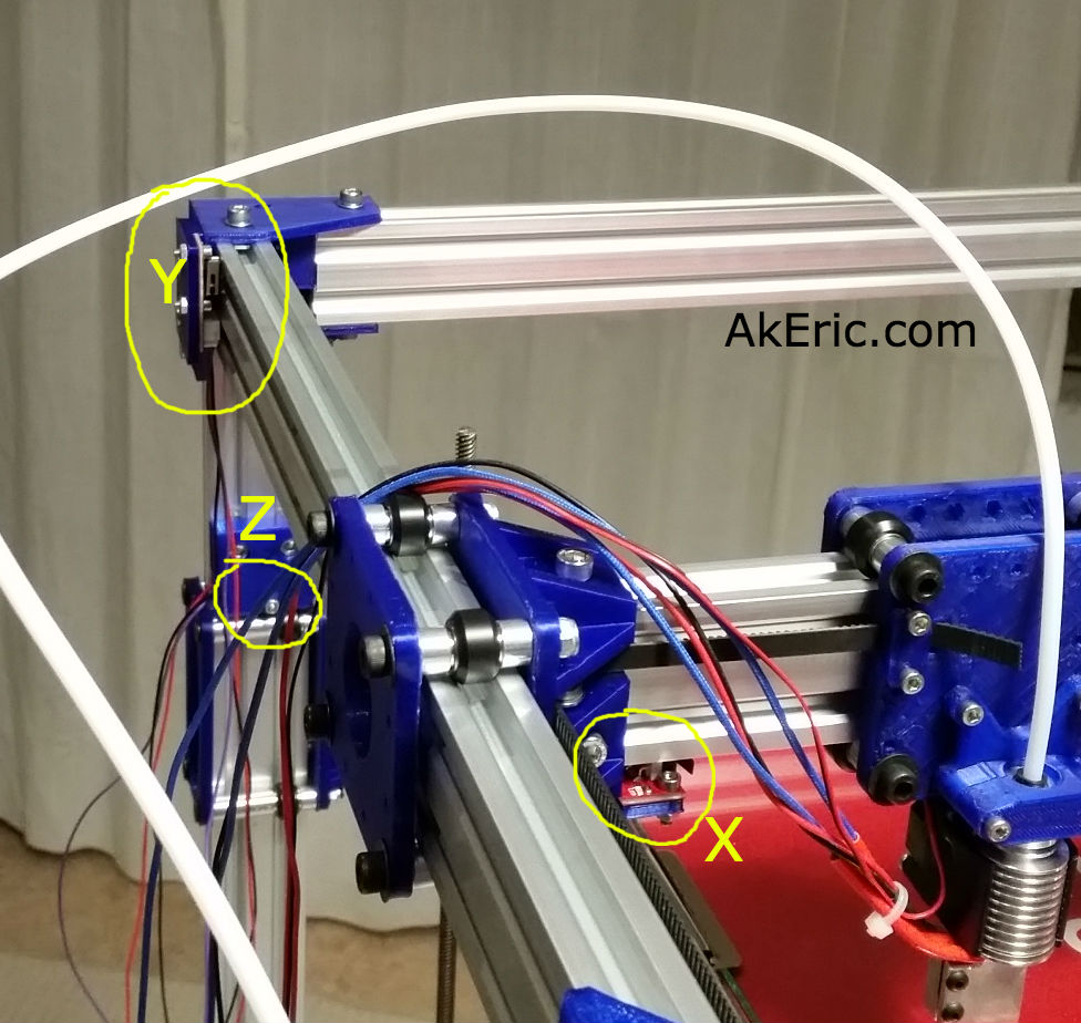
I’ve never done any start\end G-Code ‘programming’ before. The start/end G-Code for my Replicator1 was already setup.  So heading off to the ‘G-Code in Marlin‘ page, I researched what I wanted it to do on start:

  • Lower the bed a bit just in-case it hadn’t before
  • Home all axes
  • Warm up the extruder (and eventually heated bed)
  • Purge the nozzle
  • Move nozzle to edge of the bed and zero it (per the above paragraph).
  • Start print

And on end:

  • Turn off extruder and bed heating
  • Lower the z-platform slightly
  • Home XY
  • Disable motors

Another great resource is S3D itself:  Once you’ve connected to your machine, and are in the Machine Control Panel, any commands you issue show up in the Communication log:  So I set about doing each step manually, then creating the G-Code script for them.

What I came up with is currently below.  I’m sure this will change in the future.  But just in case my computer explodes I’ll have a backup here.  Note that [stuff in brackets] is S3D’s own internal syntax for embedding variables to help make the gcode more temperature agnostic.  Pretty nice.

Start G-Code:

G92 Z0 ; Set current z position to zero.
G1 Z20 ; Lower Z to be safe 20mm.
G28 ; Safe Homing of All Axes
M104 [extruder0_temperature] T0 ; Set extruder targe temp
M109 S[extruder0_temperature] T0 ; Wait for extruder current temp to reach target temp.
G1 E50.0 F600 ; Purge nozzle 50mm at 10mm/sec
G92 E0 ; zero extruder
G1 X2 Y26 ; Move nozzle to left front corner of build platform.
G92 X0 Y0 ; Zero X & Y here to start the build.

End G-Code:

M104 S0 ; turn off extruder
M140 S0 ; turn off bed
G92 Z0 ; Set current z position to zero.
G1 Z10 ; Lower Z to be safe 10mm.
G28 X0 Y0 ; Home XY
M84 ; disable motors

So I fired off my first print over USB, and ran into all sorts of weird problems over the next hour.  Long story short:

Gotchas:

  • Every time I change a setting in S3D and want to re-print, I need to turn my printer off and on.  I don’t know if this is a S3D bug, a Rumba bug, a Marlin bug, or what.  But if I don’t do this, the start G-Code won’t properly execute.  Side effects include it not heating and immediately starting a print, or heating up but then never beginning the print after it.
  • Once that was resolved, for the longest time I couldn’t get the filament to stick to the bed:  it would just curl up around the extruder.  I finally realized that a new profile I’d setup had my layer height set to 200 micron… printing with a 1mm wide Volcano nozzle:  Once I set that back to 500 micron the printing had no problems.
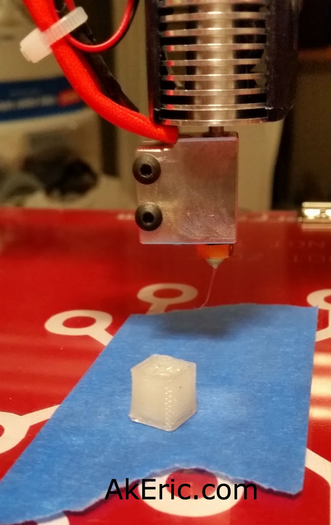
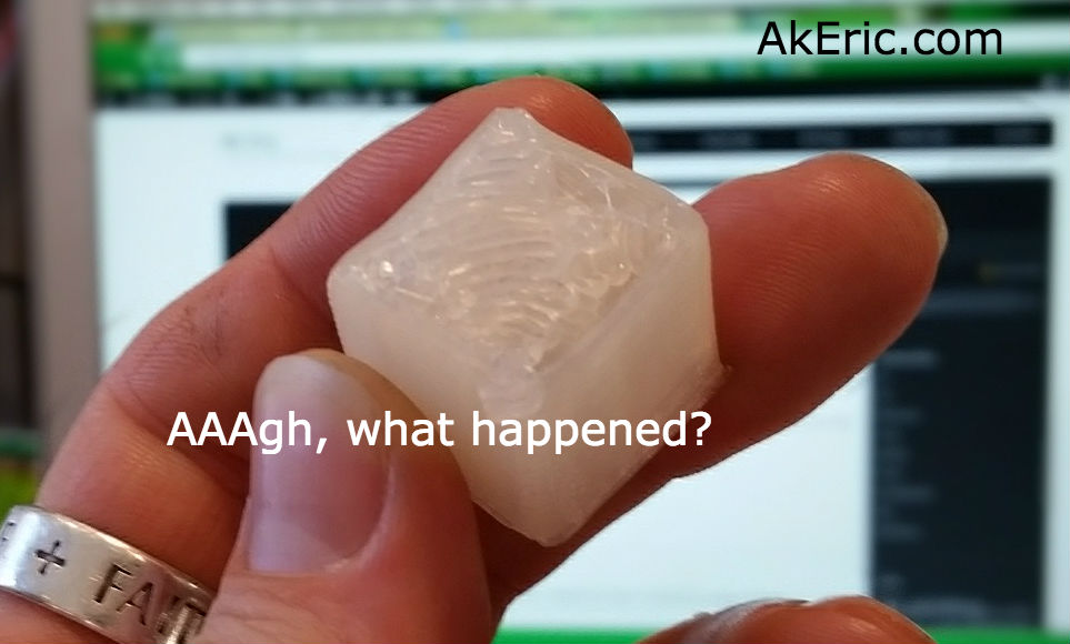
  • I really need to get a print-cooler fan installed:  I built a custom one for my Replicator 1 which has really helped.  When I finally got my printing working, and was working on a 2cm test cube, the sides looked pretty good for effectively my second print:
    • not too bad
  • But when it got to the top, the whole print was so hot that the extruded top layer filaments literally started grabbing & collapsing the side-walls.  Plus when I went to remove it when the print was done, it was soft like warm gummy bear:
    • aaaugh
  • Top priority: Get print cooler fan installed.  Or maybe a jet of liquid nitrogen…. :)

PID Autotune:


Update:  Since authoring this post I have switched my electronics to RADDS, and my firmware to Repetier.  See the “Part 31 post” for the latest on it.


While my extruder has been heating up fine, I noticed that as it approaches the target temp (say, 200c) it really slows down for the last few degrees, and takes a long time getting to the final temp.  I remember that when I switched my Replicator 2x to Sailfish firmware, the extruders stopped heating up correctly, and talking on the forums they told me I needed to update my PID settings.

PID stands for “proportional-integral-derivative“, something I did not learn about in math class.  But in a nutshell it’s a way via the maths to reach a target value smoothly and quickly, without banging/oscillating all over the place.  And luckily, Marlin comes with a PID autotune feature you can run as G-Code directly from S3D (or any software that can issue G-Code):

M303 E0 S200 C8

Fire that off when you extruder is cold, and a few minutes later it’ll spit out something that looks like this:

Recv:  bias: 213 d: 41 min: 199.38 max: 200.71
Recv:  Ku: 77.96 Tu: 13.40
Recv:  Classic PID
Recv:  Kp: 46.77
Recv:  Ki: 6.98
Recv:  Kd: 78.32
Recv: PID Autotune finished! Put the last Kp, Ki and Kd constants from above into Configuration.h

And those values you then enter back into Marlin’s Configuration.h file.

These were my original values when I authored this blog post:

#define DEFAULT_Kp 46.15
#define DEFAULT_Ki 5.10
#define DEFAULT_Kd 104.32

UPDATE (2016-01-13) :  But I found when my powerful 24cmf cooling fan would kick on to cool the Volcano nozzle, the temp would drop, and it would take a loooong time trying to catch back up.  So instead, I cranked my fan to 100% (255) and re-running the auto-pid gave me the values in the code snatch two paragraphs up.

I never timed the nozzle warmup before, my E3d-V6 Volcano now heats up from cold to 200c in 2min 10 seconds:  Not too bad.

I’ve still not got my heated bed soldered up yet (waiting on 10-gauge wire in the mail), but I’ll run this again on the bed when it’s ready.


Jump to C-Bot blog index to see all the posts.

Building the C-Bot 3D printer: Part 20 : Electronics Day 3: Swapping stepper drivers

Jump to C-Bot blog index to see all the posts.


Update:  Since authoring this post I have switched my electronics to RADDS, and my firmware to Repetier.  See the “Part 31 post” for the latest on it.


Total time:  about 3.5 hours.

My Rumba board originally came with 6x A4988 Motor Stepper Drivers that have a 1/16 microstep resolution (I won’t pretend to know that that really means.  Sounds small).  Their ‘continuous current per phase’ is rated at 1A.  I’d had previous problems trying to drive both my Z-steppers off a single driver, so I switched to a driver per stepper.  In the meantime though, I ordered a five-pack of DRV8825‘s:  They have 1/32 microstepping resolution (ooohh…) and their ‘continuous current per phase’ is 1.5A (which I figured may be enough to drive two z-steppers, which is how Mason does it).

My thought was go back to the ‘single stepper driver controls two steppers’, but since I’ve already got my paired steppers and drivers working, I’ll just leave it that way for the time being.  I may only never need to change if I decide to go to dual-extrusion.

Removing the A4988’s and swapping in the DRV8825’s was seamless: I didn’t even need to flip any of the dip-switches living under each driver, on the Rumba:  In both instances, {on,on,on} was exactly what I needed set.  However, it’s VERY IMPORTANT you mount them the correct direction (see below pic):  The trimpot on the DRV8825 mounts 180 from the A4988:  Towards the ‘top’ of the board, rather than towards bottom.  I figured this out my checking the silkscreen on both the boards and (luckily) realizing the difference.  DRV8825:  Trimpot over capacitor.  A4988: Trimpot away from capacitor.

Like before, I needed to tune them.  Previously I tuned them by adjusting their resistance (rather than voltage) values while they were un-plugged from the Rumba.  Later I found these values to be off, and ended up manually tuning them via the trimpot while driving the steppers back and forth.  Second time is always better, and I grasp the whole process more fully:

This post from the RepRap Wiki spells it out pretty plainly:  To set the reference voltage,  you take 70% of the steppers current, and divide by two.  So the maths:

How to actually tune it?  They have a nice pic on the above link, but the steps I went though were:

  • Turn on the Rumba.  I then energized the stepper drivers by manually driving the x\y gantry from the LCD.
  • Once energized, I set my multimeter to volts, touched the positive probe to the trimpot, and the negative lead to the negative pin on the driver itself.
  • From there, I’d adjust the trimpot slightly until I got to around .58v on each.
  • drv8825 tuning

    Checking the DRV8825’s reference voltage: One probe on the trimpot, the other on negative.

When that was done I thought I’d try and print the calibration cube again:  Suddenly everything started printing 2x as small.

AH!  A4988 drivers have 1/16 microstep resolution, but the DRV8825’s have 1/32 : You need 2x the steps to go the same distance.  So it was back into Marlin’s Configuration.h file to retune the ‘DEFAULT_AXIS_STEPS_PER_UNIT’ variable.  By default I doubled everything to: {200, 200, 800, 300}, then individually started tuning them via the process I used before.  My final numbers:

#define DEFAULT_AXIS_STEPS_PER_UNIT {199.7403,  200.5415,  804.90995, 300}

Noooow, I can get back to final wiring and tuning my print settings…


Jump to C-Bot blog index to see all the posts.

Building the C-Bot 3D printer: Part 19 : First print!

Jump to C-Bot blog index to see all the posts.


May as well show the good stuff first:

Even though the electronics still look like a giant pile of spaghetti out the side of the bot, there wasn’t much left stopping me from actually printing something.  But, a few things still needed addressed:

  • My build-platform wasn’t remotely level, it was drooping way too much on the front.  With the help of my wife and son, I loosened up all the bolts holding the cantilevered 20×40 beams to the Z-stage, had my son slightly lift up on the end of it, and I re-tightened everything while my wife helped hold a wrench on the rear of the nuts where needed:  That got me able to level it with some z-endstop adjustments.
  • Based on where the hot-end homes, there’s a 2mm X & 25mm Y offset from the corner of the build platform (calculated my manually moving the toolhead on X&Y via the LCD to the corner of the build platform).  I couldn’t figure out where in Marlin to enter these values:  Obviously the head needs to move to this position from home and ‘start’ the print there, as 0,0,0.  I slice using Simplify 3D, and I finally found these offsets in the “G-Code” section of the Process window, under “Global G-Code Offsets”.

I also needed to configure Simplify 3D to actually recognize this machine:  Luckily version 3.0 came out just yesterday, and has a new machine ‘Configuration Assistant’ that made the process of ‘building’ my machine pretty easy.

From there, I imported a simple 1cm calibration cube, slapped some blue painters tape on my build platform, and fired it off.  It’ immediately started moving, but not extruding:  Come to find out, even though I had all my stepper wiring in the Rumba the same, I had to flip the harness on the Bowden extruder 180 to get it to extrude the direction.  With that resolved, take two worked flawlessly:  A few minutes later, a tiny 1cm cube appeared:

first print

1st print!

This was printed with a 1.0mm E3d-v6 Volcano nozzle, at 500micron layer height.  Beefy!  Surprisingly using my calipers, it was within .02mm tolerance on all axes:  Not bad for a first print!

Safe to say I’m pretty happy that it ‘just worked’ on the first try.  Now that I know it works I’m going to clean up all the wiring next, then get into the print calibration phase.


Jump to C-Bot blog index to see all the posts.

Trouble in paradise: The Replicator quit extruding…

I’ve been using my Makerbot Replicator (1) to print all the parts for my new C-Bot build.  However as of a few days ago, it suddenly quit extruding correctly.

I print almost entirely in PLA, usually from 200-210 degrees.  Suddenly, I couldn’t get anything to print unless I raised the temp to 230-245:  Pretty crazy for PLA.  And the surface quality was terrible.  Any lower in temp and I could hear the extruder stuttering, and it wouldn’t really extrude much at all.

Leading up to this I had been printing at 120mm\sec, at .3mm layer height:  Squeezing a lot of plastic out of the nozzle at that rate.  I noticed a bunch of melted filament around the top-rear of the heater block (you only noticed it when specifically looking for it, couldn’t see it from the front\sides):  The only way it could have got there would have been backpressure from the nozzle squeezing it out of an improper location up-stream.  My guess is that this somehow started the domino effect to cause whatever was screwing up my current extrusion.  It had completely encased the back of the heater cartridge and wrapped around the thermocouple wires.  I had to heat the whole block up and carefully pick it away without damaging any of the wires.

Thanks to tips from this forum I got it resolved:  One suggestion was that the kapton tape that insulates the thermocouple had worn through, and by grounding to the heater-block it was giving inaccurate temperature readings.  This seemed like a prime culprit since I had to crank my temp settings so much higher.

I’m not sure specifically which steps fixed it, but this is what I did:

  • Did a complete teardown on the hotend, to the last bolt.  Removed old kapton, cleaned up head, wrapped in new kapton.
  • Removed heater cartridge and thermocouple : Didn’t noticed any wear-through on the thermocouple kapton, but added more just in case.
  • Did however noticed where the wire leaves the thermocouple and bends up around the heater block : one of the bends looked a bit frayed, and was mighty close to the heater block itself:  Added extra insulatory kapton at that junction.
  • Added a new nozzle, just to weed that out.
  • Re-bed level, etc.
Extrusion was immediately was back to normal after that, thankfully.  I was beginning to think the Replicator was getting jealous of the C-Bot build…. 😉
Some words of wisdom from Ryan Carlyle on the above thread:
General rule of thumb is that PLA does not print reliably over 10 mm^3/sec with a typical Replicator type hardware setup. At 0.3mm layer height, 0.4mm extrusion width, and 120mm/s, you’re doing 14.4 mm^3/sec. That’s reasonable for ABS (which melts faster) but not for PLA. Raising the temp may cover the symptoms for a while but it can also lead to charred filament and worse clogging issues later on.

Building the C-Bot 3D printer: Part 17 : Electronic & Software day 2

Jump to C-Bot blog index to see all the posts.


Update:  Since authoring this post I have switched my electronics to RADDS, and my firmware to Repetier.  See the “Part 31 post” for the latest on it.


After posting my z-stage problems to the C-bot forum, they suggested I try a couple things:  Loosen up the bolts on the ACME lead-screw blocks, and switch to using dual motor drivers, rather than one, like I’m currently doing.

I loosened things up, and it helped a negligible amount, but I was still unable to predictably raise the build platform.  So, I decided to dig into Marlin and enable dual-z-steppers.

Which I did, and then added an additional A4988 driver to the Rumba board to make use of it:

motor drivers

A4988 Drivers, with dual-z support.

I added the additional A4988 to the “Extruder 2” plug (on the far right), plugged the right z-stepper into it, and gave it a go:  The steppers would only lower, not raise.  NOW what?

Looking at the Marlin code, I noticed that the block I enabled (starting with ‘#define Z_DUAL_STEPPER_DRIVERS’) to support this looked different from the same block in the “Marlin Configurator“:  It appeared that it was also enabling “dual z endstops”, which I didn’t want to happen.  Rearranging the code resolved this, and now I have a bed that both lowers, AND raises.  Finally.  I was going to post this code-fix, but I diff’d the Configuration_adv.h file Mason had given me with the one I pulled down from GitHub, and that code section was radically different.  I’m not sure which is newer\older.  At least mine works now…


Now that I have the z-stage working, I decided to focus on the endstops:  I had mocked them up earlier, but didn’t have them wired properly… at ALL.  I spaced out and thought I only needed two wires (+-), but in reality you should also hook up signal, so the LEDs light up.  More splicing and crimping ensued, and I got the Geeetech v1.2 endstops wired up correctly, based on this great pic Mason pointed me to…

endstop diagram

… living in this thread, that explains it pretty plainly.  Thus the end results:

endstop wiring

From there, it’s getting them plugged into the Rumba correctly:

endstop connections

Note: Since I took this pic, I’ve changed my Y endstop so it is now Y-


Here’s the logic behind it:

  • Looking down on the build platform, zero XYZ is in the bottom left corner. +X is to the right, +Y is towards the back, and +Z is up.
  • The X-endstop is on the left side of the Y-gantry, that the extruder blocks hits when traveling left:  It is in the “negative” position, thus X-.
  • The Y-endstop is mounted on the top-left-rear corner of the printer, and the Y-gantry hits it when it moves back in a ‘positive’ direction.  So it’s Y+.
    • Note: Since I authored this page I’ve moved my Y endstop to the top-left-front corner, so it’s really Y- now.
  • The Z-endstop is mounted towards the top of the left rear leg of the printer, that the Z-stage hits when it lifts up.  Since when the build platform drops it’s going in a ‘positive’ direction (or, instead, imagine the build platform on the bottom of the printer, and the nozzle lifting up instead, which is effectively the same thing), it means it starts at the negative position, thus -Z.
endstop locations

Note: Since I took this pic, I’ve changed my Y endstop so it is now Y-, or on the front-left of the bot, rather than rear-left as in this pic.


Once the endstops were wired up, I was able to ‘auto home’ the whole system from the LCD, and… it worked.

Finally, no more blockers… next up will be calibrating the XYZ travel distances.


Jump to C-Bot blog index to see all the posts.