Posts Tagged ‘ A4988

Building the C-Bot 3D printer: Part 28 : Lighting, Ringing, Breaking

Jump to C-Bot blog index to see all the posts.


This update is a combo post on several subjects at once:

Adding Lighting

Up until now, the C-Bot has been a dark printer:  No internal lighting whatsoever.  My Replicator1 is like a little supernova next to it when the room is dark.  But no longer:  Over the weekend I added both an 12v LED strip to the top-front X-beam (pointing directly at the print-bed) and a superbright LED directly on the print-head itself:
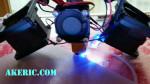
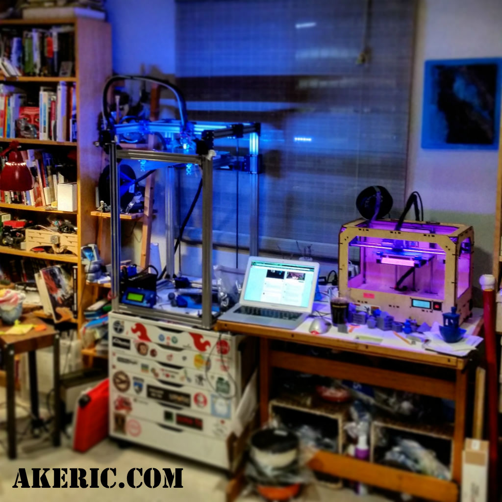
While my buddy Mason did a slick job of wiring his LED strip directly into the Rumba board on his C-Bot, so he can adjust the lighting based on the print settings, I did not:  I ran a extra 12v lead out of my power-supply, and connected both the LED Strip, and the superbright LED (with inline resistor) directly to it:  Turn C-Bot on, lights turn on.  Nuff’said / good enough.

Breaking

After I installed the lighting and turned the bot back on, the Bowden extruder suddenly started jittering:  It would no longer extrude filament.

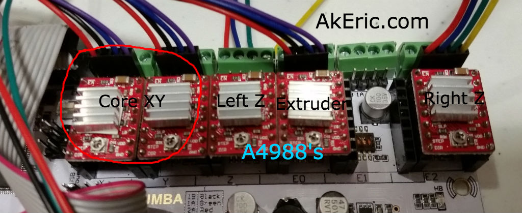
I started by swapping a DRV8825 stepper driver from the z-steppers to the extruder stepper slot:  Try extruding, and it works.  Ok, it must be a bad DRV8825, and I have no spares.  But I do have a bunch of extra A4988‘s:  I’ll just put one in there, and updated my firmware to use it instead.  It doesn’t work:  Jittering starts again.  So I revert the firmware change, and put a ‘good’ DRV8825 back in:  Jittering.  What is going on?

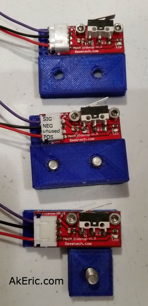
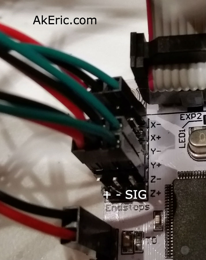
Soon, any DRV8825 I put in that slot causes jittering, but they all work when plugged back into their original slot.  Drivers are good,… is my board bad?  At this point I disconnect the 4-prong JST connector running from the board to the stepper, and notice that one side is slightly melted: I remove the wires from the connector, and connect them on-by-one to the pins on the board:  Everything starts working again.

Canibalizing a connector from some other wires, I reinsert the leads, plug it into the board, and back in action.

Seriously?!?

Improving Ringing / Ghosting

I had recently printed out a “Sledgehammer Games Recognition Coin Holder” for someone at work (I modeled it in Maya / Tinkercad):  We can give out cool coins to fellow employees for doing good work, and I designed this coin holder so people can show them off (there’s four slots in the top to hold the coins).

I’d printed many on my Replicator 1 in the past, and printed this one on the C-Bot for the first time.  And what I noticed was, there was a terrible amount of ghosting / ringing happening:

shg_recognition

Click to see the full-size that really shows the problem off.

This was printed with the .6mm E3D-Volcano nozzle, 300 micron layer heights at 60mm/sec, in MakerGeeks Royal Purple PLA.

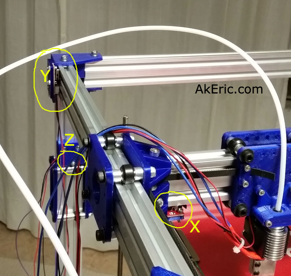
The issue was, the prints done on my Replicator 1 had less ringing than the C-Bot, and this didn’t make sense to me:  The C-Bot has a Bowden extruder, thus removing a bunch of moving mass from the toolhead, not to mention it uses Core-XY mechanics, that is supposed to help out as well.  Why are things worse?

Posting this question to the 3D Printing Google Group, I got a bunch of good answers.  Specifically, my firmware acceleration may be too high, and the size of the printer itself could be causing too much shake, do to the lack of additional cross-members for stability.  Right now I have no surplus extrusions to stiffen it up, and my ultimate goal is to bolt the printer directly to the wall, thus really locking down any shaking.  But in the meantime, I can adjust the acceleration in the firmware.

I made a ringing/ghosting test model in Maya that would show off the issue on X, Y, and XY all at the same time.  I printed it with my default settings (3000 mm/sec), then dropped it waaay down to 800 mm/sec.  The results were pretty obvious:

ringing_comparison

Click for bigger pic

On the left of each image, is the ‘800 mm/sec acceleration’ print, and on the right is the ‘3000 mm/sec acceleration’ print.  These changes were made in Marlin’s Configuration.h:

#define DEFAULT_ACCELERATION 800
#define DEFAULT_RETRACT_ACCELERATION 800
#define DEFAULT_TRAVEL_ACCELERATION 800

I just set everything that looked applicable to 800.

So, an noticeable improvement.  But once I get the printer “bolted down”, I hope to be able to print even faster, with better results.


Jump to C-Bot blog index to see all the posts.

Building the C-Bot 3D printer: Part 20 : Electronics Day 3: Swapping stepper drivers

Jump to C-Bot blog index to see all the posts.


Update:  Since authoring this post I have switched my electronics to RADDS, and my firmware to Repetier.  See the “Part 31 post” for the latest on it.


Total time:  about 3.5 hours.

My Rumba board originally came with 6x A4988 Motor Stepper Drivers that have a 1/16 microstep resolution (I won’t pretend to know that that really means.  Sounds small).  Their ‘continuous current per phase’ is rated at 1A.  I’d had previous problems trying to drive both my Z-steppers off a single driver, so I switched to a driver per stepper.  In the meantime though, I ordered a five-pack of DRV8825‘s:  They have 1/32 microstepping resolution (ooohh…) and their ‘continuous current per phase’ is 1.5A (which I figured may be enough to drive two z-steppers, which is how Mason does it).

My thought was go back to the ‘single stepper driver controls two steppers’, but since I’ve already got my paired steppers and drivers working, I’ll just leave it that way for the time being.  I may only never need to change if I decide to go to dual-extrusion.

Removing the A4988’s and swapping in the DRV8825’s was seamless: I didn’t even need to flip any of the dip-switches living under each driver, on the Rumba:  In both instances, {on,on,on} was exactly what I needed set.  However, it’s VERY IMPORTANT you mount them the correct direction (see below pic):  The trimpot on the DRV8825 mounts 180 from the A4988:  Towards the ‘top’ of the board, rather than towards bottom.  I figured this out my checking the silkscreen on both the boards and (luckily) realizing the difference.  DRV8825:  Trimpot over capacitor.  A4988: Trimpot away from capacitor.

Like before, I needed to tune them.  Previously I tuned them by adjusting their resistance (rather than voltage) values while they were un-plugged from the Rumba.  Later I found these values to be off, and ended up manually tuning them via the trimpot while driving the steppers back and forth.  Second time is always better, and I grasp the whole process more fully:

This post from the RepRap Wiki spells it out pretty plainly:  To set the reference voltage,  you take 70% of the steppers current, and divide by two.  So the maths:

How to actually tune it?  They have a nice pic on the above link, but the steps I went though were:

  • Turn on the Rumba.  I then energized the stepper drivers by manually driving the x\y gantry from the LCD.
  • Once energized, I set my multimeter to volts, touched the positive probe to the trimpot, and the negative lead to the negative pin on the driver itself.
  • From there, I’d adjust the trimpot slightly until I got to around .58v on each.
  • drv8825 tuning

    Checking the DRV8825’s reference voltage: One probe on the trimpot, the other on negative.

When that was done I thought I’d try and print the calibration cube again:  Suddenly everything started printing 2x as small.

AH!  A4988 drivers have 1/16 microstep resolution, but the DRV8825’s have 1/32 : You need 2x the steps to go the same distance.  So it was back into Marlin’s Configuration.h file to retune the ‘DEFAULT_AXIS_STEPS_PER_UNIT’ variable.  By default I doubled everything to: {200, 200, 800, 300}, then individually started tuning them via the process I used before.  My final numbers:

#define DEFAULT_AXIS_STEPS_PER_UNIT {199.7403,  200.5415,  804.90995, 300}

Noooow, I can get back to final wiring and tuning my print settings…


Jump to C-Bot blog index to see all the posts.

Building the C-Bot 3D printer: Part 18 : Software Day 3 : Tuning movement settings

Jump to C-Bot blog index to see all the posts.


Update:  Since authoring this post I have switched my electronics to RADDS, and my firmware to Repetier.  See the “Part 31 post” for the latest on it.


Now that my z-stage is moving down and up, and I can ‘auto home’ my printer through the LCD, it was time to get the movement settings and max travel extents calibrated.

Total time:  About two.5 hours.

Tuning Movement Settings:

You need to make sure that when the g-code tells your printer to go 100 mm’s, it really goes 100mm.  Not 90mm.  Not 100.1mm: 100 mm.  On bots like my Makerbot Replicator (1) this is already done for you.  But when building your own machine from scratch, you need to figure all this out.  Otherwise you get ovals where you should get circles, and rectangles where you should get squares.

First I had to get some info for my hardware:

  • Stepper :
  • Stepper Driver:
  • XY Pulleys:
    • GT2
    • Teeth : 16
  • Belts:
    • GT2
    • Pitch : 2mm (distance between each tooth)
  • Lead Screw :
    • 8mm ACME
    • Pitch : Listed at 2 (distance in mm between each peak), but this value was incorrect for the below calculator.  Info below.  The value needed in this instance was 8 (the distance in mm traveled with one revolution).

Armed with those numbers, I accessed the “RepRap Calculator” to get me the base values for my bot.  I wanted to see if they’d match values Mason had already pre-plugged into Marlin (that mine should very closely match), but I wanted to understand how this system worked:  In Marlin’s Configuration.h, I found the line with ‘DEFAULT_AXIS_STEPS_PER_UNIT’ with an array of four values plugged into it {x, y, z, extruder}.  Based on the calculator, my ‘belt steps per mm’ came out to 100, which was around what Mason had given me.  However, the ‘leadscrew steps per mm’ were 4x (1600) what was listed in the firmware (400).  After a bit of research, I realized the calculator wanted to know the distance the lead screw travels in one revolution, not the tooth-to-tooth pitch (2mm).  Armed with my calipers, I figured out one revolution traveled 8mm, and plugging that into the calculator gave me a value of 400.  Success!

Now for the tuning:  I found this great guide (on the Marlin Configuration page) by Neil Underwood that goes through the manual process of telling your bot (in my case, via the LCD) to go 100mm, and then measure with calipers to see how far it really went.  Do maths, enter new values into firmware, re-measure, over and over.  Not hard, just a bit time consuming:

My final values:

#define DEFAULT_AXIS_STEPS_PER_UNIT {100.2166,  100.20469,  401.770921, 145.5687675196672}

Gotchas:

I just hit one major problems:  Very often the Rumba would reject the upload from the Arduino IDE.  At a certain point, it took me half an hour to get three uploads.  It turned this already slow process into an incredibly slow and frustrating process.

I’ve been programming Arduino’s for years and never encountered anything like this (but never on a 2560 like the Rumba uses):  Sketch would compile, but when it would go to upload it would timeout, saying this:

avrdude: stk500v2_ReceiveMessage(): timeout

Searching the internets, I found many other people with complaints (not Rumba specific, Arduino Mega specific), but no solutions.  Finally, I read one post (which I’ve lost the link to) that had this issue.  The fix?  Simply swapping USB ports on your PC between uploads.  Suddenly I was back in business.

Setting the max travel extents

For each axis, there is an endstop telling the printer to ‘stop moving’ when it hits it.  Most printers (like mine) only have one endstop per axis, although you could setup two per axis (min & max) and probably skip this step.  If the endstop stops the toolhead\build platform going in one direction, what stops it going in the other?  The firmware.

In Marlin’s Configuration.h, there’s a section called “Travel limits after homing”, where you can setup these constraints for X, Y, and Z_MAX_POS.  To start, I edited these values to be something much larger than my current volume, since I was going to dial this in manually on my own and didn’t want a small value to stop me before the true extent was reached.

After re-uploading the firmware with the ‘big’ values, via the LCD I manually drove each X, Y & Z axis to what I considered was the ‘safest max position’: Just before a X/Y gantry would hit something on the opposite side with maybe 10mm to spare, or about 50mm above the lead screw flexible couplings so as to not cause any binding.  I copied those numbers down from the LCD and plugged it back into the firmware.  My final values are:

// Travel limits after homing (units are in mm)
#define X_MIN_POS 0
#define Y_MIN_POS 0
#define Z_MIN_POS 0
#define X_MAX_POS 320
#define Y_MAX_POS 315
#define Z_MAX_POS 530

So my X & Y are clearly over a foot (304.8 mm), so I have no problem filling my whole 12×12″ bed.  But the Z is just under 21″, 3+” short of the 24″ build height I was after.  This is due to a few reasons:  I have maybe an inch before the z-gantry hits the flexible couplings on the leadscrews, and my E3D volcano easily sticks down over 2″ from the X/Y-gantry : If I did a bit of redesign on the extruder mount I could probably move it ‘up’ more and get 2+” back, and I’d be closer to my 24″ height goal.  But 21″ isn’t too shabby to start… 😛

Other Notes:

In my previous post I showed how my Y-endstop was at the rear of the bot:  This actually blocked the gantry from moving all the way back, and since the extruder is mounted on the front of it, I couldn’t get all the way to the rear of the build platform:  I moved it to the front corner instead, and got that clearance back.  Now my  endstops are all Xneg,Yneg,Zneg, when before they were Xneg,Ypos,Zneg.  In the firmware, the settings are thus:

// ENDSTOP SETTINGS:
// Sets direction of endstops when homing; 1=MAX, -1=MIN
// :[-1,1]
#define X_HOME_DIR -1
#define Y_HOME_DIR -1
#define Z_HOME_DIR -1

Jump to C-Bot blog index to see all the posts.

Building the C-Bot 3D printer: Part 17 : Electronic & Software day 2

Jump to C-Bot blog index to see all the posts.


Update:  Since authoring this post I have switched my electronics to RADDS, and my firmware to Repetier.  See the “Part 31 post” for the latest on it.


After posting my z-stage problems to the C-bot forum, they suggested I try a couple things:  Loosen up the bolts on the ACME lead-screw blocks, and switch to using dual motor drivers, rather than one, like I’m currently doing.

I loosened things up, and it helped a negligible amount, but I was still unable to predictably raise the build platform.  So, I decided to dig into Marlin and enable dual-z-steppers.

Which I did, and then added an additional A4988 driver to the Rumba board to make use of it:

motor drivers

A4988 Drivers, with dual-z support.

I added the additional A4988 to the “Extruder 2” plug (on the far right), plugged the right z-stepper into it, and gave it a go:  The steppers would only lower, not raise.  NOW what?

Looking at the Marlin code, I noticed that the block I enabled (starting with ‘#define Z_DUAL_STEPPER_DRIVERS’) to support this looked different from the same block in the “Marlin Configurator“:  It appeared that it was also enabling “dual z endstops”, which I didn’t want to happen.  Rearranging the code resolved this, and now I have a bed that both lowers, AND raises.  Finally.  I was going to post this code-fix, but I diff’d the Configuration_adv.h file Mason had given me with the one I pulled down from GitHub, and that code section was radically different.  I’m not sure which is newer\older.  At least mine works now…


Now that I have the z-stage working, I decided to focus on the endstops:  I had mocked them up earlier, but didn’t have them wired properly… at ALL.  I spaced out and thought I only needed two wires (+-), but in reality you should also hook up signal, so the LEDs light up.  More splicing and crimping ensued, and I got the Geeetech v1.2 endstops wired up correctly, based on this great pic Mason pointed me to…

endstop diagram

… living in this thread, that explains it pretty plainly.  Thus the end results:

endstop wiring

From there, it’s getting them plugged into the Rumba correctly:

endstop connections

Note: Since I took this pic, I’ve changed my Y endstop so it is now Y-


Here’s the logic behind it:

  • Looking down on the build platform, zero XYZ is in the bottom left corner. +X is to the right, +Y is towards the back, and +Z is up.
  • The X-endstop is on the left side of the Y-gantry, that the extruder blocks hits when traveling left:  It is in the “negative” position, thus X-.
  • The Y-endstop is mounted on the top-left-rear corner of the printer, and the Y-gantry hits it when it moves back in a ‘positive’ direction.  So it’s Y+.
    • Note: Since I authored this page I’ve moved my Y endstop to the top-left-front corner, so it’s really Y- now.
  • The Z-endstop is mounted towards the top of the left rear leg of the printer, that the Z-stage hits when it lifts up.  Since when the build platform drops it’s going in a ‘positive’ direction (or, instead, imagine the build platform on the bottom of the printer, and the nozzle lifting up instead, which is effectively the same thing), it means it starts at the negative position, thus -Z.
endstop locations

Note: Since I took this pic, I’ve changed my Y endstop so it is now Y-, or on the front-left of the bot, rather than rear-left as in this pic.


Once the endstops were wired up, I was able to ‘auto home’ the whole system from the LCD, and… it worked.

Finally, no more blockers… next up will be calibrating the XYZ travel distances.


Jump to C-Bot blog index to see all the posts.

Building the C-Bot 3D printer: Part 16 : Assembly Updates

Jump to C-Bot blog index to see all the posts.


While I struggle with getting my Z-steppers to work, I did some frame upgrades:

  • I hadn’t ordered enough of the OpenBuilds ‘Black Angle Corner Connectors‘ : I needed 18, I bought 8 (not sure how I missed that)…  Mason needed extras as well, so he placed a big order, and I got my ten in today.  So, I swapped out my printed corners on both the bottom of the frame, and the parallel arms under the HPB with the new corners.  Metal FTW!
  • The 8x 55mm M5 bolts that held the wheels onto the Z-gantry weren’t long enough:  I couldn’t actually got a nut on the back-side.  Mason experienced the same issue, and picked up two 10-packs of 60mm M5 bolts and gave me one:  I went through the process, one at a time, of removing those bolts from the wheel assembly on the HPB, and swapping it for the new 60mm version, with a locknut on the end.  I held all the existing spacers, wheels, and shims in place (so they wouldn’t fall all over the floor when I removed the bolt) with tape on the bottom:  Worked great!

Thoughts on my Z-stepper issue:

  • The A4988 drivers (that came with my Rumba ) ‘continuous current per phase’ is 1A (see link).  The DRV8825‘s (like what Mason uses) are 1.5A.  I’m wondering if that 50% boost would be enough to lift the z-stage?  I found a 5-pack on Ebay for $13, so those are on order.  But it can take up to a month:  Mason may have a spare, and if so, I can test this out and see if the extra power is worth it.
  • I spent a good amount of time making sure my rear Z-extrusions were the exact width apart, and futzing with the HPB Z-stage brackets:  I can now lift the gantry with one hand with little resistance.  I also made sure the Z-steppers were exactly below the ACME lead-screw holders:  I can now get the HPB to lower, just not raise (without help from my hand).  So again, I hope the DRV8825’s will resolve this lifting issue.

Time tonight:  About 2 hours.


Jump to C-Bot blog index to see all the posts.