Historical Notes
I think I first started caring about beer in the mid 2000’s: I was plenty old enough to drink it, but I didn’t really enjoy it up until then: The macro brands I grew up with never tasted good to me (just because you can do something doesn’t mean you should). Even when I’d ask my imbibing friends it if they liked it, they’d just sort of shrug their shoulders. It was more of a means to an end for them, the destination was far more important than the 12-pack journey.
Around that time my best friend moved to Portland, OR, and when I’d go and visit him we’d visit ‘brewpubs’ : Magical places where you could drink the (really good!) beer they made on site, and eat food. Was nothing like I’d experienced anywhere else at the time, despite having lived in places like LA, Honolulu, and San Francisco. Suddenly, beer was good. Just not near me. The beer aisle in Safeway was still entirely filled with case after case of macro brands.
Since I lived near San Francisco at the time, which is really close to the Napa, Sonoma, and Mendocino wine-growing regions, I branched into wine full-force for the next 10 years. I still enjoyed a good beer, but they continued to be hard to find in any abundance. Great wine was everywhere however, so it was easier to pick that low-hanging fruit off the tree of fermentation.
During that same time, my father and younger brother (in Alaska none the less) both got into the homebrew scene, and started knocking out tasty beers (& wines) I’d get to sample when we’d visit one another. Then around the early 2010’s craft-brew really started taking off in the SF bay, and I dived in, visiting as many local breweries as I could. Wine is still an amazing product, but my pallet shifted, hard into the land of malt and hops. Safeway shifted too: Only one small corner of that aisle had any macro: The rest was all craft. Safeway carrying craft beer? The zeitgeist of the time was definitely swaying.
One final trip to Portland in winter 2017 cemented my future, after an old high-school buddy (now a distributor of brewery supplies) gave me his copy of Charlie Papazian’s “The Complete Joy Of Home Brewing” (while meeting at a brewery none-the-less) : I read that cover to cover over the next few days, and my fate was sealed: In Jan of 2018, I brewed my first beer.
Below I will recount my first homebrew experience.
Research
This sections recounts areas of research I found valuable before I got started. Off the bat I decided to go with a malt-extract process rather than all-grain. All grain takes longer, more up-front cost… and for all I know at the end of the day, despite how much I enjoy drinking beer, I had no idea how much i’d enjoy making beer.
Books
These were books provided to me, and I’m glad they were:
I have a number more… just not got a chance to read them yet.
Videos
There are… many video’s on youtube for brewing. These are some good into-level / informative video’s that I think do a pretty good job of explaining things. While some of these cover all-grain (and I’m doing malt extract) they’re still applicable.
Equipment
Like mentioned above, I’m doing malt-extract brewing. No all-grain yet, so my equipment list below reflects that (for example, no mash tun). I purchased most of my gear from Amazon and MoreBeer.
I’m told you can make totally fine beer out of a bucket system for $100-$200 (the buckets are usually only $5-$10 a piece, that other cost is just for all the other gear you need), and I have no reason to doubt that. However, I wanted something I could easily grow, and I like ‘new tech’, so I didn’t go the bucket route. Because of that, my spreadsheet tells me I spent around $750 on the below setup, not counting the additional costs required to build-out my space. However, moving forward, my only major costs are that of the beer ingredients, and the gas/electricity to heat/power things.
Fermenter
I did a lot of research into what type of fermenter I wanted to get for my first homebrew setup. Three main options for the homebrewer presented themselves:
- Plastic buckets: Cheap, work just fine. More siphoning required between primary & secondary (+ bottling bucket), not a big deal though with an auto-siphon.
- Plastic conical: More up-front cost that buckets, but allows for primary and secondary fermentation in the same vessel (if you’re into doing such things) since it’s so easy to drop the trub from the attached container on the bottom. Downside is they’re not as easy to move around as buckets, and you need custom freestanding mounts or brackets on your wall (which may or may not be a downside based on your space).
- Metal conical : Way more expensive than plastic, looks great, lasts longer, but similar end results.
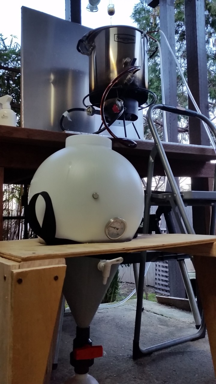
In the end, after much research, I decided to go with: 7.9gal FastFerment conical.
However, if money wasn’t an issue, I think it’d be hard to go wrong with the SS Brewtech 7 gal Chronical Fermenter. Beautiful, but 4x the cost.
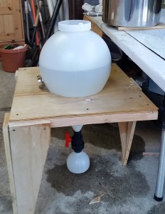
The only main complaint I’d heard from people about the FastFerment was that the top wouldn’t seal well. And when I got it, I experienced a similar problem : Trying to screw that lid on, I just couldn’t get it to sit/seal right. I was frustrated. However, this ended up not being an issue at all: While trying to ‘screw it on dry’ gave me grief, when I did my first brewday runthough (just using water), it screwed on just fine: Having a little bit of water/sanitizer in there made it tighten up with no issues and seal fine.
In addition to the basic things that come with it (airlock, tubing, etc) I also picked up the sampling port (convenient for taking gravity readings), carrying strap, and thermometer for its built-in thermowell.
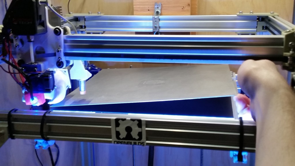
Here it is in my scrap-wood-creation to hold it (I didn’t want to pay extra for the metal frame) during my initial leak-test (it passed just fine) :
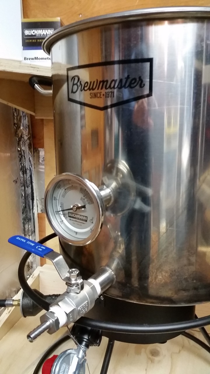
Brew Kettle
I went with the ‘8.5 Gallon Brewmaster Stainless Steel Brew Kettle, plus a screw-in thermometer for the extra port. The bottom port works great for gravity-transferring wort into my fermenter. I didn’t think much of it at the time of purchase, but the silicon handles are pretty nice too.
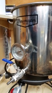
I wanted a larger size kettle to help avoid boil-overs, and brew larger batches if I wanted too.
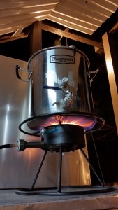
Propane Burner
I love beer but the Mrs does not, so I need to do all my brewing outside. I picked up ‘The Dark Star Propane Burner 2.0‘ and it’s treated me fine so far. Sounds like a jet engine.
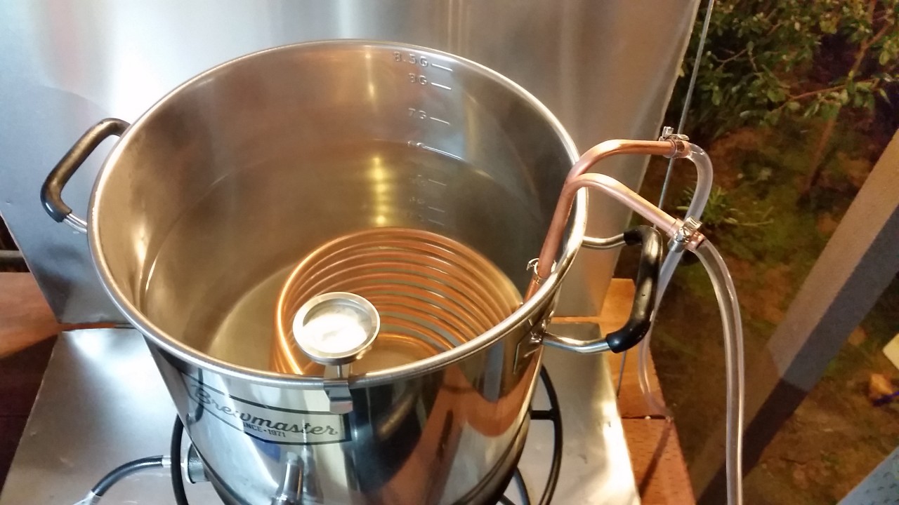
Immersion Chiller
Got this one off Amazon. I was going to build it myself until I figured out the price of materials was only around $10 away from having that shipped to me. Worth it. While you don’t need an immersion chiller, the faster you can chill your wort the better, and I wanted to set myself up for success.

Water Supply
We get our water from Hetch Hetchy, near Yosemite. I’m told its ‘great water for beer’, but that doesn’t mean the pipes getting it to my house are. Not to mention fluoride and chlorine can be added. Since I’m getting my water from a garden-hose faucet on the side of my house, I picked up both a water filter, and food-safe garden hose to do the transfer.
Fermentation Chamber
After much reading and discussion with other hombrewers, one of the biggest ‘failure points’ they’d experienced was keeping the correct consistent fermentation temperature. If making ales, anything from 65-75 (very rough numbers) seemed like a safe temp, and most people keep their homes within that range most of the time. However, one homebrewer commented that one day in the summer, the temp hit the high-90’s, and that batch of beer was ruined.
My house is small, so I had no room to store my fermenter in it. But I do have room in my workshop for it. However, the workshop is uninsulated, and it could hit mid-30’s on a cold CA winter night, or over 100 on a hot summer day. I needed something to keep the beer at the right temp.
I found a number of devices to heat or cool the fermenter, but rarely at the same time. I finally found a heat-exchanger that sits in the top of the fermenter (the BrewJacket), and can both heat and cool. But it was close to $300-$400. If I ever wanted to get another fermenter and do two brews at once, I’d have to get another $300-$400 doodad. This seemed overly expensive, despite the convenience (I really wanted to get one…).
After seeing several designs online, I decided to build my own fermentation chamber. Carving out a corner of my shop, I set to work installing a false-floor (most of my workshop is a dirt floor), table to sit all the gear on, and finally the chamber itself:
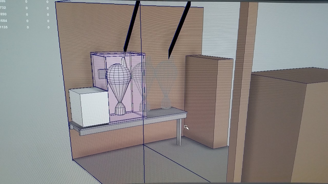
First I mocked the whole thing up in 3D to make sure it would all fit:
 < Looking x-ray through my workshop wall. Everything brown is pre-existing.
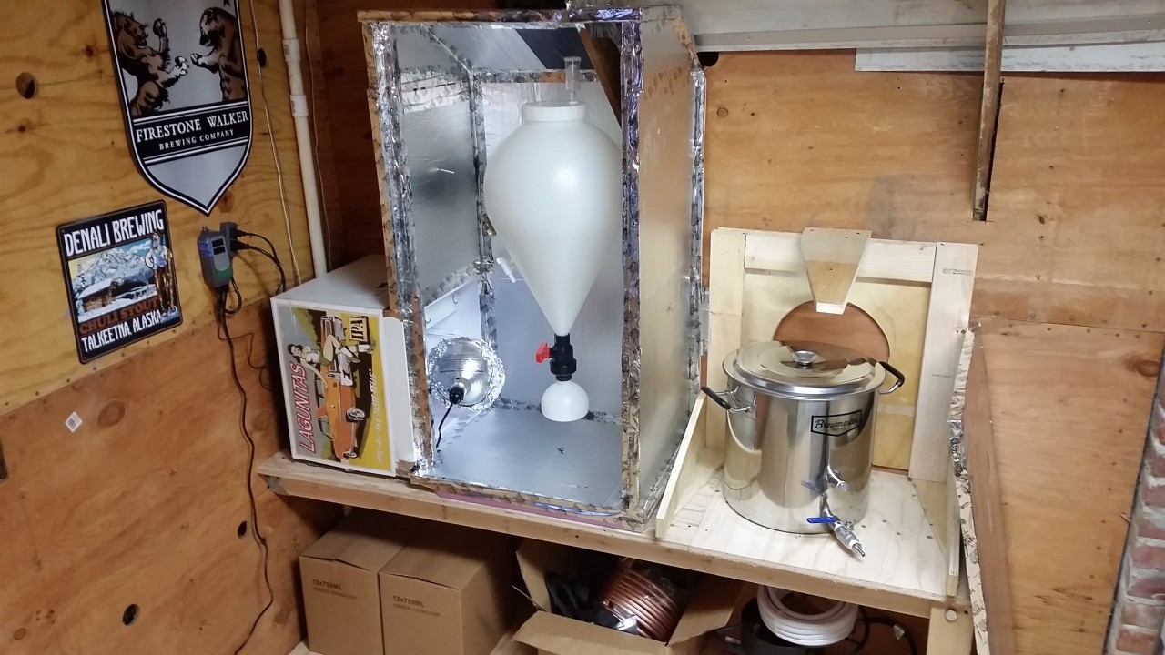
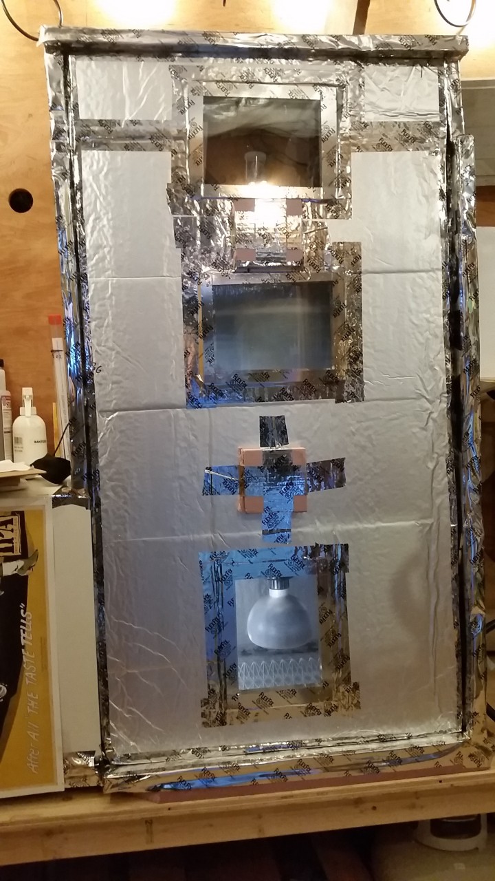
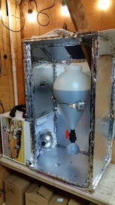
Then got to the construction:

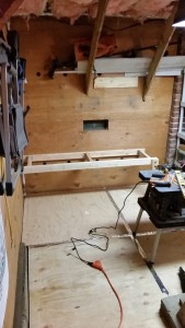

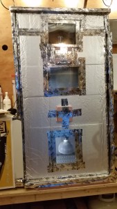
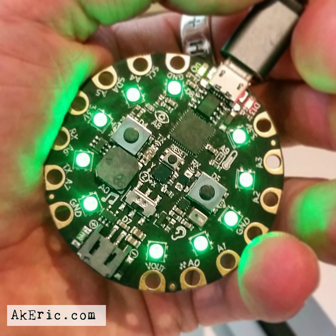
I used 1″ aluminum-faced foam board to insulate the chamber. Found a $30 mini-fridge on Craigslist for the cooling, and used a 150w bulb to provide heat, all hooked up to an Inkbird Digital Temp Controller (seen hanging on the wall in the 3rd pic). I cut some portholes in the ‘door’ seated with rectangular Plexiglas, sealed up on either side to form an insulatory air-chamber in the middle : I can now see the airlock, the top of the beer in the fermenter, and the collection ball in the bottom at all times, even with the door closed. I also wired in a small low-speed muffin-fan that runs at all times, to keep the air circulating.
Sanitizing & Cleaning Products
For sanitization, I went with Star San, and for cleaning I’m using Five Start PBW.
Bottles
I decided to go with 750ml amber swing-tops: Two cases of 12 would do a 5-gal batch nicely, and I don’t have to wory about capping the bottles. Plus, if I don’t finish the bottle (rare), it stays nice and sealed in my fridge.

Other Gear
Other items of note include: Both steel (for stirring the wort) and plastic (for stirring the fermenter) 24″ brew spoons, two spray bottles (one for filterd water in case of boilovers, the other for spray-on sanitization), Hydrometer & Hydrometer jar, bottle filler wand, several reusable nylon bags for hops & specialty grains, extra food-grade vinyl tubing as needed.
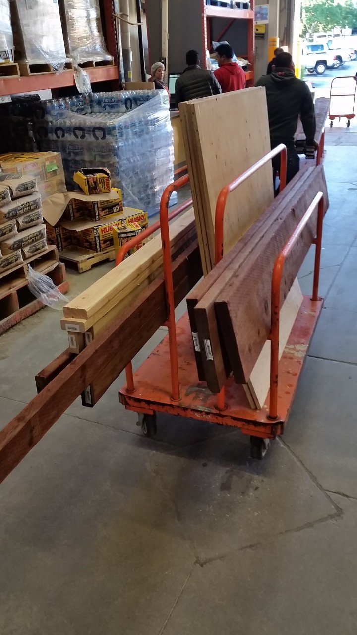
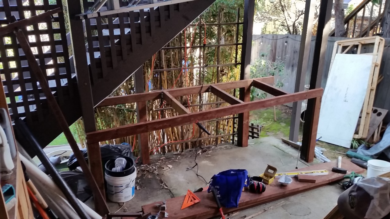
Brewing Outdoors
Shown above is the fermentation chamber and gear storage area in my workshop. But I brew outside, so I needed a space to do that. A space I didn’t yet have. So, construction commenced:

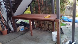
Now I had something to put my outdoor brewing equipment on.

The above pic shows it all: I do my boil on the (new) elevated bench which allows for easy gravity-feeding into the fermenter when complete. I had previously made a sheet-metal covered L-shaped (foldable) frame I used for welding on: I put my burner on that for an extra level of safety.
Brewday
Step By Step Guide
Before my first brewday, I did a complete run-through the the whole process using water. For someone that had never brewed before, this was an invaluable setp, and allowed me to make a step-by-step guide for my future self: I found nothing so succinct online. You can find that doc here: Extract Brewing: Brew Day: Fast Ferment. Even if you don’t use a FastFerment, this is a good resource for anyone wanting to get into this hobby to see every exact step you’ll need to go through to brew an extract beer.
My First Beer
The first beer I choose was a ‘B3 Stout’ extract kit by MoreBeer. I wanted something familiar, that shouldn’t be too hard to brew. For the yeast, I went with Wyeast 1056 American Ale.
Process
Overall, it went off without a hitch: I had a number of buddies over to help move things around, check temps, stir, etc, and it was really appreciated. Could I do this by myself? Sure. Would it be as fun? Heck no 😉 And again, the doc I link to above lists the exact steps I went though.
The whole thing, from the start of the boil to the end cleanup took just around 3 hours.
Things of note:
- Like everything else you read, sanitization is king. No, StarSan won’t hurt you, I got it all over myself with no ill effects.
- Even watching the temp, the wort definitely tried to boil over. Having that spray-bottle on-hand to get it down was really effective.
- My base malt-extract came in a really big bag, and has the consistency of honey. I intentionally didn’t warm it up to see the effect while pouring it: Safe to say, I will be pre-warming it in the future, it’ll simply make it easier to pour out, and get more of it out.
- I was never too sure if I activated the ‘smack pack’ successfully in the yeast: But after siting out for an hour, it had definitely swollen up, which was a good sign.
- Took about 25 minutes running the immersion chiller to hit 72 deg, to pitch the yeast.
- Before I pitched the yeast, I took a gravity reading, it was at 1.065.
From there, I hauled it over to the fermentation chamber, got it locked in, and turned on the temp control. Within a few hours it had settled on 65 deg, and stayed there for the next two weeks.
 Just before the door goes on for a week…
Above, you can see how I taped the temperature probe onto the side of the fermenter. There’s a lot of discussion on the best place to put these, and I found more votes for this solution than others. Based on the end results, I’d have no reason to change it.
Tracking The Fermentation Process
While fermentation can continue even after the airlock stops bubbling, it’s still a pretty good indication of what’s going on in there (or so I read). I tracked the “BPM” (bubbles per minute) for the first week, here are the results:
- Day #1 : (brewday) Not much.
- Day #2 : Many bubbles (but I hadn’t started recording yet)
- Day #3 PM : 70 BPM
- Day #4 AM : 30 BPM
- Day #4 PM : 20 BPM
- Day #5 AM : 12 BPM
- Day #5 PM : 5 BPM
- Day #6 PM : 1 BPM
- Day #7 PM : 1 bubble every 1min 30 sec.
On Day 8, I did the ‘secondary transfer’ (below), then let it ferment for another week (which as you’ll read below, was probably unnecessary(?)).
Secondary Transfer
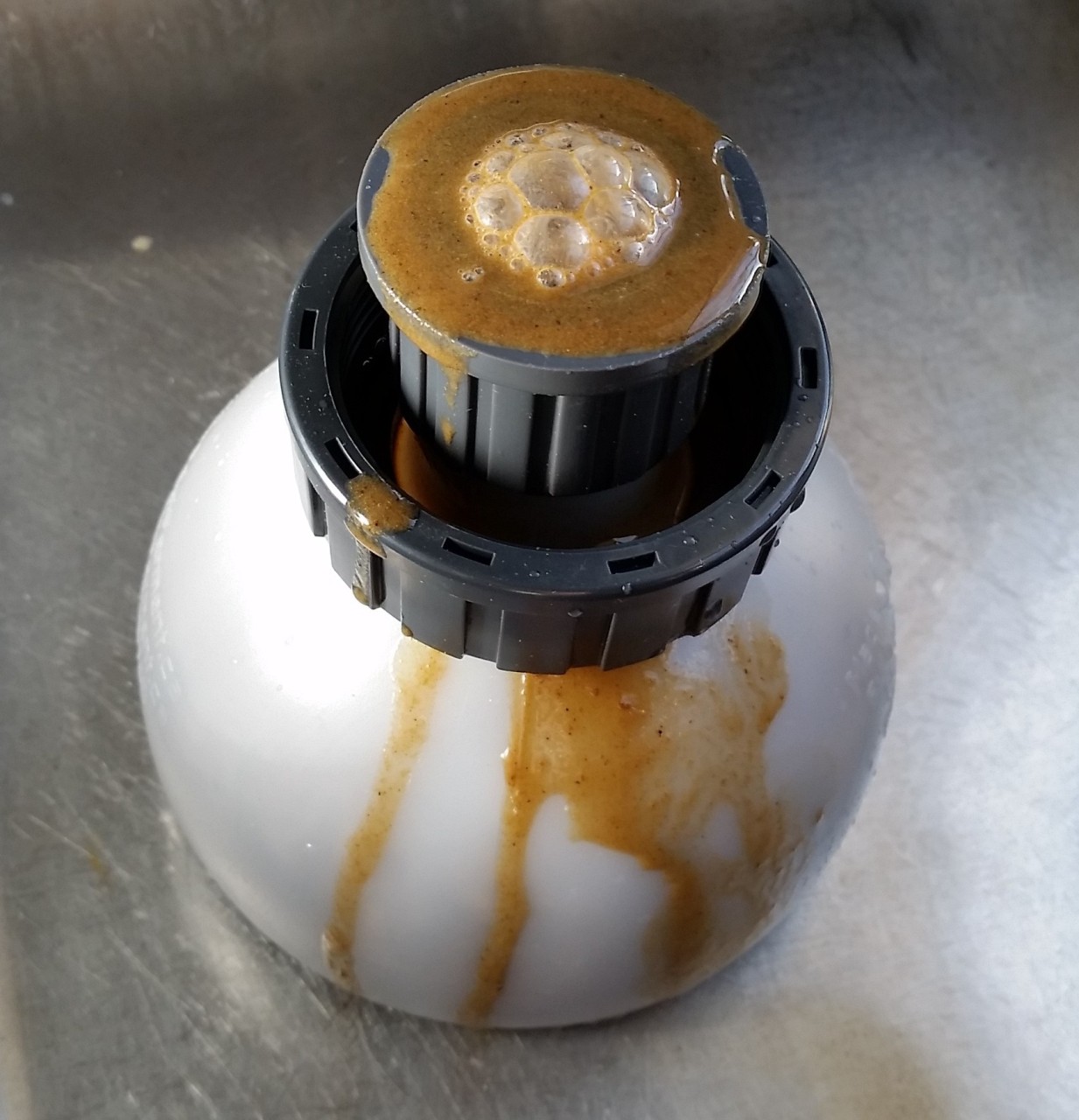
There is plenty of discussion on whether or not you need to ‘transfer your beer to a secondary’ on the homebrew arena (all depending on the type of beer you’re making). Passionate arguments on either side of the fence. With the FastFerment though, why not? There is no ‘transfer’ to speak of : You simply close the collection ball value, and dump the trub out. Figured I’d give it a shot.
After a week of fermentation, I decided to ‘drop trub’, and it worked as advertised:

Whole collection ball was full of brown goo I washed down my drain.
Also took a gravity reading from the sampling port: Read 1.020
From there, I reinstalled the collection ball, re-opened it allowing the exiting beer (and any other trub) to drop in, and let it sit for another week of fermentation.
Bottleday
After two weeks of fermentation, I bottled. On that day I took my final gravity reading: 1.020 : The exact same number as week ago… telling me fermentation actually only took one week.
Which means this beer clocks in at 5.9% ABV. Respectable.
I closed the collection ball valve and removed it: It was maybe 2/3 filled with trub, the rest beer, that all got dumped. At which point I screwed on the bottle-filler attachment from the bottom: No need to transfer to a ‘bottling bucket’: You can bottle directly off the bottom of the FastFerment. I have no pics of this process, but the FastFerment website has videos of it (linked above).
(Update/Edit) : The MoreBeer kit came with priming sugar I first boiled, then added directly to the fermenter and stirred it up with my spastic brewspoon (so as not to scrape the insides with the stainless one).
Had two other buddies over, and with them, we went though a process of:
- Buddy #1 sanitizes bottles, hands me one.
- I fill it with the bottling wand & close the swing-top.
- I hand it to buddy #2, who takes it outside, washes it off, and stores it in a box.
Took, maybe an hour?
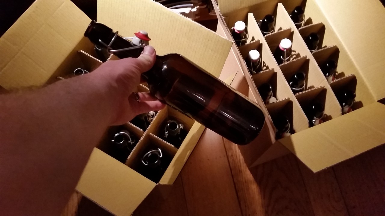
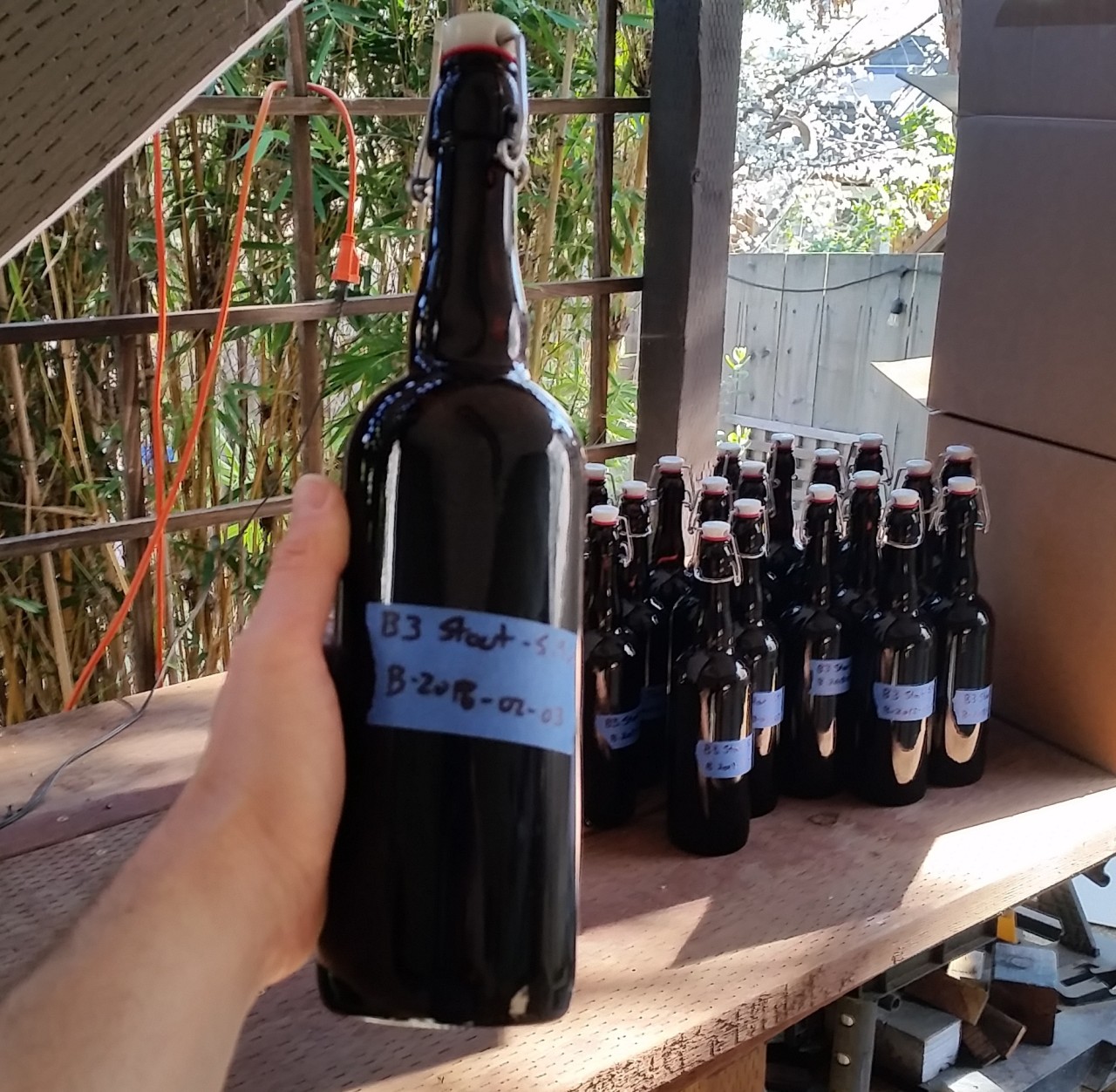
End result, beauty:

The Verdict
Packed in their two 12-unit cardboard boxes, I let them bottle age in the fermentation chamber for two weeks at 65 degrees.
I had planned on bringing some into work on a Friday to share with people. So, that Friday AM I cracked one open for the first time to sample it. Much anticipation….
Ugh, it tasted pretty bad. But in hindsight, for three main reasons:
- It was 8am. I don’t think I’ve ever had a beer at 8am.
- I just brushed my teeth. Peppermint toothpaste + dark stout do not mix.
- It was room temperature.
I figured my palette was off and the beer was too warm, so I brought a few bottles in a cold pack anyway.
I was very pleasantly surprised that evening that it actually tasted pretty good. In fact, everyone that tried it lauded how good it was. Some more than others, but it was an entirely positive reception. All the bottles were quickly drained.
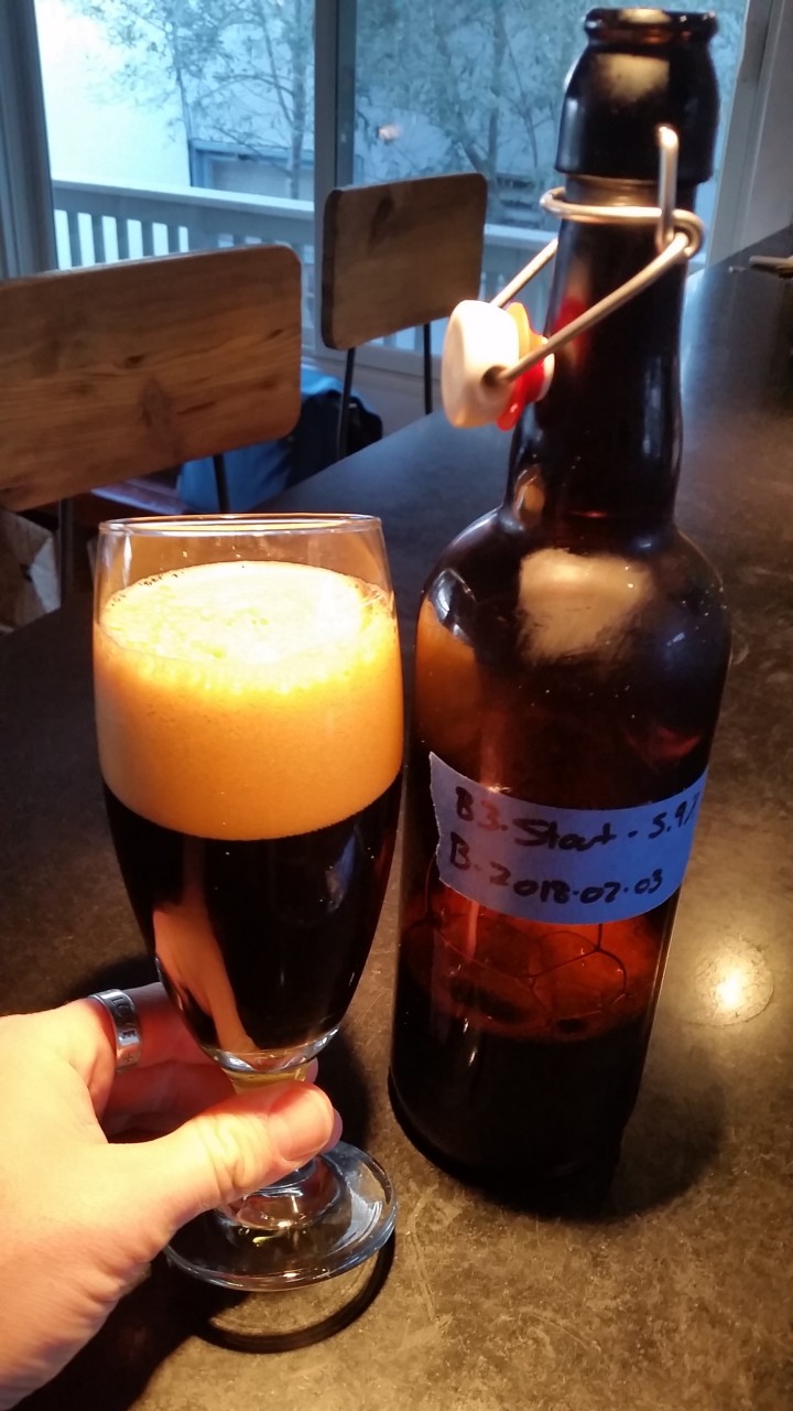
It’s March 3rd as I type this, a month after bottling, and honestly they continue to get better: The was some initial bitterness on the end I didn’t care for, that’s all but gone now. It’s evolving into a smooth malty/roasty stout that goes down really easy. When you crack open the swingtop it pops like a champagne bottle, and it pours a thick creamy head. A very good first try!
 (the head is a nice light brown… that light is just really yellow)
I’m really looking forward to doing this again! Definitely an extremely positive first experience.
Things I think helped get me success:
- A lot of reading & research ahead of time.
- Dry (well, wet) runthrough ahead of time.
- Making my step-by-step guide for the brewday was invaluable.
- OCD sanitization.
- Fermentation chamber with hot & cold temp control.
- Good water.
- (seemingly) quality ingredients.
And as Charlie Papazian says all through his book: “Relax! Don’t Worry! Have a homebrew.”