Building the C-Bot 3D printer: Part 11 : Assembly Day 5
Jump to C-Bot blog index to see all the posts.
Today I knocked out The Y-gantry, and the X-Gantry/hotend. Total time: About three hours.
As usual, there were some gotcha’s:
- Somehow, the file that created the print of two plates that the G2-belts and hot-end bolt to was mirrored: All the files I had, were reversed, so that the belt clamps were in the wrong location (bottom instead of top and vice-versa). So I had to scale that model and reprint 2x of them.
- After getting all the X-Gantry/hotend wheel assemblies staged, I realized I was short one ‘mini v-wheel precision shim‘: Either I was shorted one, or I lost one. Luckily I can trade Mason for some t-nuts 😉
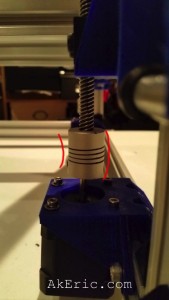
- From the previous day’s build: The shimmed angle the z-steppers have to be at to connect with the lead-screws is just too extreme: Should be perfectly straight. Either Mason or I will need to update the ‘ACME Block Holder’ stl to ‘push it out’ more & reprint.
-

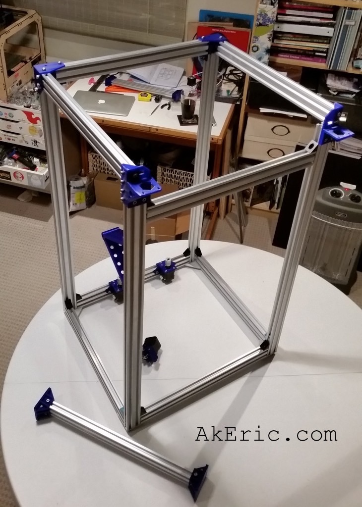
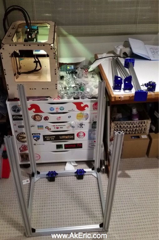
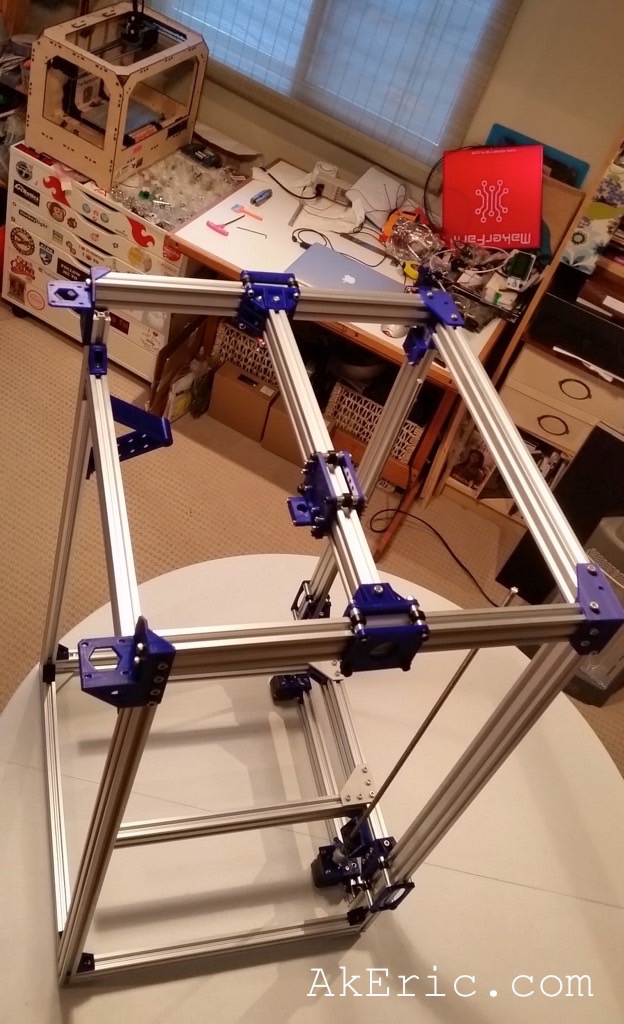
- Day 11 progress
-

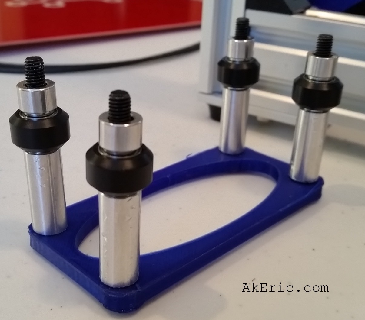
- Y-Gantry rollers
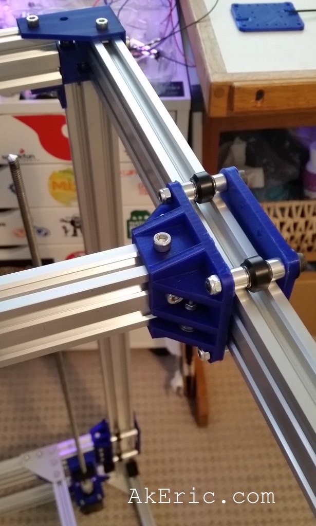
-
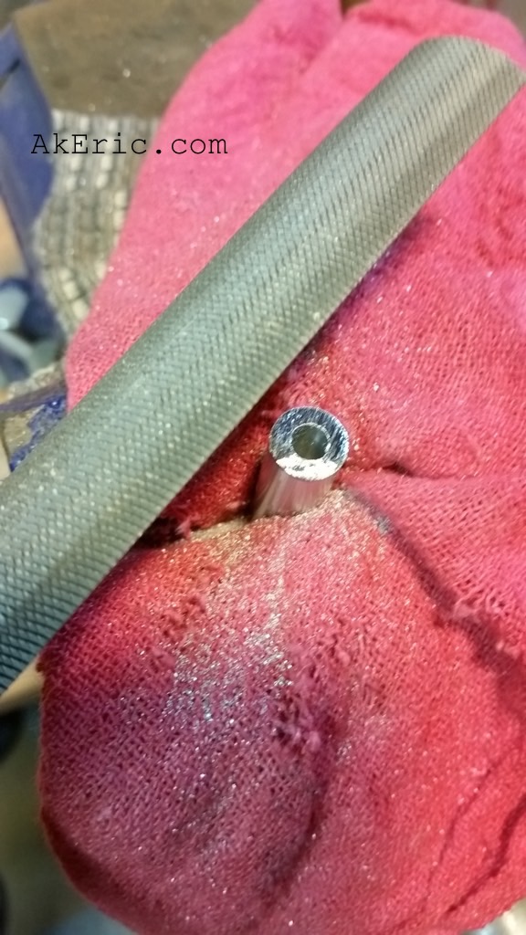
- X-Gantry rollers

Jump to C-Bot blog index to see all the posts.