Archive for the ‘ projects ’ Category

Building the C-Bot 3D printer: Part 16 : Assembly Updates

Jump to C-Bot blog index to see all the posts.


While I struggle with getting my Z-steppers to work, I did some frame upgrades:

  • I hadn’t ordered enough of the OpenBuilds ‘Black Angle Corner Connectors‘ : I needed 18, I bought 8 (not sure how I missed that)…  Mason needed extras as well, so he placed a big order, and I got my ten in today.  So, I swapped out my printed corners on both the bottom of the frame, and the parallel arms under the HPB with the new corners.  Metal FTW!
  • The 8x 55mm M5 bolts that held the wheels onto the Z-gantry weren’t long enough:  I couldn’t actually got a nut on the back-side.  Mason experienced the same issue, and picked up two 10-packs of 60mm M5 bolts and gave me one:  I went through the process, one at a time, of removing those bolts from the wheel assembly on the HPB, and swapping it for the new 60mm version, with a locknut on the end.  I held all the existing spacers, wheels, and shims in place (so they wouldn’t fall all over the floor when I removed the bolt) with tape on the bottom:  Worked great!

Thoughts on my Z-stepper issue:

  • The A4988 drivers (that came with my Rumba ) ‘continuous current per phase’ is 1A (see link).  The DRV8825‘s (like what Mason uses) are 1.5A.  I’m wondering if that 50% boost would be enough to lift the z-stage?  I found a 5-pack on Ebay for $13, so those are on order.  But it can take up to a month:  Mason may have a spare, and if so, I can test this out and see if the extra power is worth it.
  • I spent a good amount of time making sure my rear Z-extrusions were the exact width apart, and futzing with the HPB Z-stage brackets:  I can now lift the gantry with one hand with little resistance.  I also made sure the Z-steppers were exactly below the ACME lead-screw holders:  I can now get the HPB to lower, just not raise (without help from my hand).  So again, I hope the DRV8825’s will resolve this lifting issue.

Time tonight:  About 2 hours.


Jump to C-Bot blog index to see all the posts.

Building the C-Bot 3D printer: Part 15 : Software Day 1

Jump to C-Bot blog index to see all the posts.


Update:  Since authoring this post I have switched my electronics to RADDS, and my firmware to Repetier.  See the “Part 31 post” for the latest on it.


Instaling Marlin

Once all the wiring was mocked up, was time to get Marlin installed:  The Rumba already had a cut of Marlin on it, but I need an updated version turning on the coreXY mechanics.

Spent probably 4 hours on this….

The steps I went though were:

Installed latest Arduino IDE.

Downloaded zip of Marlin off of GitHub.

Copied the unzipped /Marlin-Release/Marlin subfolder to my /Documents/Arduino folder.

Copied the unzipped/Marlin-Release/ArduinoAddons/Arduino_1.5.x/hardware subfolder to my /Documents/Arduino/hardware folder.

Followed the “Quick Started Guide to program” on the Rumba page to do the initial tweaks to Marlin.

Uploaded and, the LCD screen stopped working >:-(

So I went to the RepRapDiscount Smart Controller page to glean what it had to say:  I wants you to set your board type to ’30’, which ain’t a Rumba, and other things that didn’t seem to apply to my board.

Mason sent me his cut of Marlin, and after I got it installed my LCD came back.  I need to diff files and see what I did wrong and he did right.  He did remember that he ‘had to go modify the LCD code to get it to work’.  Scary!

Tuning the stepper drivers

(Note, I have since replaced these with DRV8825’s, check out this post to see a better way to tune them up).

Once the LCD was working, I could start manually tuning the A4988 motor stepper drivers.  My previous post talks about the math to calculate the values, but that sort of goes out the window when you turn things on.  From the “Motor Calibration” section of the RepRap Wiki, they say:

“Each Pololu has a trimpot located next to the heatsink. The trimpot controls the current that is sent to each motor. Turning the trimpot counter-clockwise reduces the current to the motor, turning it clockwise increases the current to the motor.

Start by adjusting the trimpot down until your motor vibrates on the spot rather than turning cleanly. Now turn the trimpot in a clockwise direction in small increments (1 eighth of a turn) until the motors just start running. Then give the trim port a final turn of about 1 eighth of a turn and your should be good to go.”

So I did a bunch of that and got the X/Y steppers working, + the extruder.  But I couldn’t get my dual-Z steppers to work.  I had both stepper wires running into the same green terminal blocks.  Mason suggested maybe I connect one to the terminal blocks, and the other to the pins behind it:  That made things seemingly work better, but the z-stage still wouldn’t move.  I loosened the couplings that hold the leadscrews to the steppers, and then they’d start to turn.  But if I tighten them back up, no movement.  Currently stuck here.  Grrr…


Jump to C-Bot blog index to see all the posts.

Building the C-Bot 3D printer: Part 14 : Electronics Day 1

Jump to C-Bot blog index to see all the posts.

printing spaghetti monster

Spaghetti!


Update:  Since authoring this post I have switched my electronics to RADDS, and my firmware to Repetier.  See the “Part 31 post” for the latest on it.


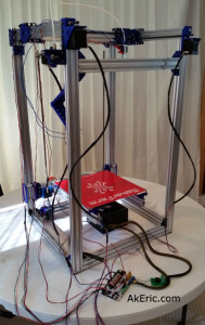
Today I mocked up the bulk of the electronics:  Connecting wires, running cables, plugging them all into the Rumba.  The only ones I wasn’t able to complete were the wires for the extruder heater block and the HPB themistor, since my soldering iron broke.  I also wasn’t able to wire the the HPB relay fully, since I don’t have any extra 10awg wire laying around, that I’ll need to solder to the HPB leads.  But other than that, all the electronics got wired and hooked up.

Total time:  Around five hours.

Overall I:

  • Went to the electronics store and got all sorts of various JST connectors and whatnot to get everything hooked up.
  • Connected all wires to components, and into the Rumba (see gotchas below).  My Rumba kit came with a bunch of wires, which made this pretty easy.
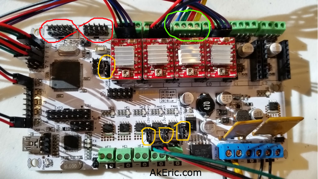
  • Should call out that since I have two z-steppers, they both get slaved to the same stepper driver:  They both plug into the same terminals.  In the below image, this is circled in green.
  • Hooked up the LCD screen (see gotcha below).
  • Set the stepper drivers current limits (details below).
  • Turned it on.  Not much I can do since I need to update the firmware to recognize the Core-XY geometry.  But at least it turns on and I can play with the menus :)

Still need to:

  • Get some nice wire-wrap to cover all the bundles of wires.
  • Get more 10awg wire to hook up the HPB.
  • Find the final routing solution for all the wires.
  • Finish up the HBP and thermistor wiring/soldering.

Notes from the day:

The Rumba hardware I bought on Ebay:

Docs:

Handy pics I printed:

I had these around me all the time, made it easier to figure out where things went.

Jumper Settings:

There are several jumpers that need to be set on the Rumba.  My Rumba only came with one, but you need to set four total.

  • Be sure to set the jumper (to the left of the left most stepper driver) to 12v power, not the 3.3v USB.
  • Above the right three green mosfet terminals, there are jumpers:  Set each of them on to bottom two pins, setting them to 12v power.

In the below image, the jumpers are circled in yellow:

rumba

Red = flipped silkscreen. Green = Double z-steppers. Yellow = Jumpers. Note the order of the stepper wires circled in green is wrong in this shot.

Tuning the stepper driver current limit:

(Note, I have since replaced these with DRV8825’s, check out this post to see a better way to tune them up).

The OpenBuilds Nema 17 steppers I purchased can draw 1.68A per phase, according to the web page.  The A4988 Motor Stepper Drivers, from their page, list their ‘maximum current per phase’ at 2A:  It’s higher than our steppers can draw, and that’s good :)

driver tuning
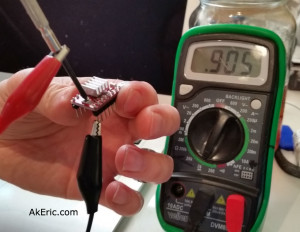
There appear to be a variety of ways of setting the current limit, but a way that Mason used is this :  Using alligator clips, connect one lead from your multimeter to the ground pin on the A4988, and the other to a small screwdriver:  You can then put the screwdriver in the trimpot and check the resistance :  For the A4988, you want to set it to just under 2.5x what the stepper can draw (you can find this formula under the ‘Current Limiting’ section of the A4988 page linked to above).  My stepper can draw 1.68A, that divided by 2.5 would be .672, or 672 ohm on my multimeter.  Note, after going through all these steps, I learned that the value on the multimeter actually needs to 10x that amount: So I’ll got just a bit under, and set it to 6500 ohm.   It should be noted that other stepper drivers have different values.  For example, the DRV8825 (what Mason’s using) divides by 2, not 2.5.

ALL THAT BEING SAID, none of it really mattered later, when I went to go dial in the settings manually (later post).  So maybe it’s a good place to start, but ultimately doesn’t seem to matter.

VERY IMPORTANT:  When you go to install the stepper drivers in the Rumba, be sure to insert the stepper drivers in with the trimpot “down”, or away from the capacitor beneath it.  See my above image for reference.  I found docs online describing this, and telling me to do the exact opposite (which would probably blow the drivers):  As it turned out, this was for a RAMPS 1.4 board, rather than a Rumba 1.4 board. Close one!

Gotchas:

  • So when I looked at the Nema-17 wiring harness, I realized that the order of the wires changed down the length of the harness.  This is shown in the below image.  So, I went through every single end terminal and swapped them out to the same as the other end, thinking this was correct. It is not, just leave it alone.  I got to swap it all back again :S
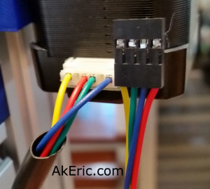
    • From this diagram, A/Green, A-/Yellow, B/Red. B-/Blue
    • From the Rumba Board:  1B/Black, 1A/Green, 2A/Red, 2B/Blue
    • But… comparing those two things makes absolutely no sense since both the colors and A/B descriptors differ.  According to Mason he plugged his into the board in the order RBGY, and it works, so that’s what I’ll do.
  • The silkscreen on the Rumba is wrong when it comes to the two smart-display ribbon cables:  When I first turned it on, the LCD didn’t light up, and it just made a slow beeping sound.  After doing some searching, I learned that the skilkscreen for that area on my Rumba was both reversed, and backwards.  Meaning, I needed to plug the ‘exp1’ cable into ‘exp2’, and the ‘exp2’ cable into exp1.  And, they both had to be rotated 180 degrees.  Crazy!  In the above image, this is circled in red.
  • My soldering iron died.  So sad.

Jump to C-Bot blog index to see all the posts.

Building the C-Bot 3D printer: Part 13 : Assembly Day 7

Jump to C-Bot blog index to see all the posts.


My final day of hardware assembly:  Mason brought in the missing bolt I needed to finish the HPB installation.  I also picked up a pair of ‘Astrosyn Nema 17 Isolation Mounts’ from a friend of Mason’s:  I’m told these can really help with stepper vibration to improve print quality:  I installed them on each of the Core-XY steppers.

On a side note, if you don’t feel like ordering them from England, there’s a guy on a forum here selling them in the US (only).  At the time of this blog he still has some available.

I also got the Core-XY belts ran with the help of my son.  So at this point truly, all the hardware is in place:  Nothing stopping me from the electronics next.

I printed out a case for the Rumba board.  My Rep1 was having a terrible time with extruder jams and extruder skipping.  I’ll probably need to print it again to get better quality :S

Gotchas:

  • When installing the isolation mounts I realized the M3x10mm bolts holding in the steppers in would need to be cut down to 5mm.  So back down to the workshop with the Dremel & vice to cut eight of those.
  • I’d forgot to load the appropriate T-nuts for the Rumba case and control panel (when I finally print it):  So I had to pull off the bottom two legs, load more nuts, and re-measure stuff as I tightened everything up.

Here’s some closeups of the latest:


Jump to C-Bot blog index to see all the posts.

Building the C-Bot 3D printer: Part 11 : Assembly Day 5

Jump to C-Bot blog index to see all the posts.


Today I knocked out The Y-gantry, and the X-Gantry/hotend.  Total time: About three hours.

As usual, there were some gotcha’s:

  • Somehow, the file that created the print of two plates that the G2-belts and hot-end bolt to was mirrored:  All the files I had, were reversed, so that the belt clamps were in the wrong location (bottom instead of top and vice-versa).  So I had to scale that model and reprint 2x of them.
  • After getting all the X-Gantry/hotend wheel assemblies staged, I realized I was short onemini v-wheel precision shim‘: Either I was shorted one, or I lost one.  Luckily I can trade Mason for some t-nuts 😉
  • From the previous day’s build:  The shimmed angle the z-steppers have to be at to connect with the lead-screws is just too extreme:  Should be perfectly straight.  Either Mason or I will need to update the ‘ACME Block Holder’ stl to ‘push it out’ more & reprint.

Jump to C-Bot blog index to see all the posts.