Posts Tagged ‘ arduino

Arduino 4wd robot & Ping))) sensor

More photos at the bottom. Click to enlarge.

Armed with the knowledge of my previous “Ponar” post, I successfully completed construction and programming of my “Arduino-based 4wd robot with servo-actuated Ping))) sensor”.   It was an enjoyable process with a lot of trial and error since: I’m still learning a lot about how the Arduino works, how hardware hooked up to it works, and electronics work in general.  To get things started, here is a video of it driving around my kitchen:

Here’s the parts list:

Here’s the Arduino program:

How it works:

  • I wanted a simple robot to drive around avoiding obstacles using the ping sensor.  To do that, I sketched out (on paper) the general program, that went like this:
    • Ping to see if there is any obstacles in front.
    • If not, drive forward, while pinging.
    • If there is an obstacle, stop, and take a distance reading to the left and right of the robot.
    • Turn for a fixed period of time in the further direction.
    • Ping again:  If still blocked, keep turning that direction.  If not blocked, go back to drive mode.
  • There are basically three modes the robot can live in:  Drive forward (mode 1), stop and scan (mode 2), and turn (mode 3).  When driving, it can do three things:  Drive straight, turn left, turn right.
  • The hardware is configured like so:
    • The Adafruit Motorshield is plugged into the top of the Arduino.
    • The Arduino is powered off of 5xAA batteries (7.5v) in the belly of the robot.  These are wired to a switch sticking out the back of the robot.
    • The Motorshiled is powered off a separate 4xC battery pack (6v) on top of the robot.  These are wired to another switch on the back of the robot.
    • The 4 DC wheel motors & servo are powered off the Motorshield.
    • The Ping))) sensor draws power form the Arduino.

Things Learned:

  • Next time, use 2-wheeled robot instead:  easier to steer around the house.  The “tank steering” method of this robot seems like it uses a lot of power and doesn’t work very good.
  • I read it in a couple places, and it turns out it’s probably needed:  Solder a 1uf capacitor between the leads on the DC motors to help “smooth out” their operation.  Otherwise it seems little “hiccups” can happen while driving.
  • Voltage, voltage, voltage:
    • I was having all sorts of problems getting the motors to work properly:  They’d start\stop “hiccuping” a lot.  Per the above note I added in extra capacitors on the motors themselves, but it didn’t solve all the problems:
    • Originally I had the motors hooked up to the 5xAA battery pack (7.5v) that came with the robot chassis.  The motors per the specs are rated at max for 6v.  But… I didn’t know this.  I thought it needed moar power.  So I went out and got a 6xC (9v) pack and powered the motors through that.  The stuttering got even worse (although, it went pretty fast when it behaved) and even did something really stupid:  Put one of the batteries in backwards… which caused it to melt-down and leak acid everywhere.  Sigh…
    • Finally (after I knew the correct voltage for the motors and servo) I went out and got a 4xC pack (6v), and that, combined with the extra capacitors, finally gave it a smooth ride.
  • I had to solder in extra connections to the analog pins on the motorshield to allow fo the Ping))) sensor to passthrough it to the Arduino (acting as a digital pin).  However, the motorshield has the pins in the order of “signal\-\+”, while the cables from the Ping))) (and servo) are “signal\+\-“.  Not sure why the motorshield would break ordering convention, but I had to splice and re-wire the Ping))) cable to match the board.
  • The motorshield docs say that servo2 is pin9, but it’s actually pin10.  That took me a while to figure out… :-S
  • I ran into a lot of problems with the programming of the robot itself:
    • The behavior is to run, ping, scan, repeat.  But during “scan” it wouldn’t drive the servo full left\right:  Sometimes it would only  got left, never make it right.
    • To solve this, I put a “timer” in the code, that would only execute the main loop if a certain amount of time in ms had passed (30ms to be exact, which makes it run around 30fps in game terms).  This seemed to make it behave exactly how I wanted.
    • I thought I needed to tell the motors to run on every loop:  It turns out they’re a state machine:  once you tell them to run, they keep running until you tell them otherwise.  Knowing this helped me clean up the code.
  • There doesn’t seem to be any official documentation I could find to the motorshield library, I had to crack open this header file to deduce what it could do:  AFMotor.h

Picture time!  Click to enlarge:

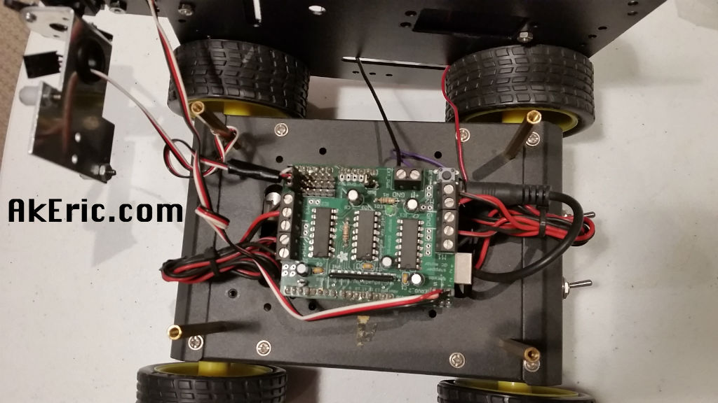
And a final shot of the wiring on the board per request:

arduino_4wd_wiring

Ponar

While at the last Maker Faire, I picked up a 4wd robot kit.

My thought is to hook an ultrasonic sensor to it, to do some simple obstacle avoidance.  Since I’ve never worked with any of these components before (servo’s, ultrasonic sensors, motor-drivers, etc), I want to break down each step so I can really grasp how this stuff works.

I was looking at my bucket of parts and it dawned on me:  I have a servo, I have a Ping))) sensor, a spare Arduino Uno, a bunch of Erector Set parts, and knowledge of Processing programming:  I could (should!) make a simple sonar system.  So the “Ponar” was born:  Ping))) + Arduino + Servo + Processing = Ponar.

How it works:

The Arduino program sweeps the servo back and forth over a 90deg arc.  At each degree, the Ping))) sensor returns back a distance reading.  The degrees and distance values are passed over the serial port to the PC, where the Processing application turns them into a ‘traditional looking’ (in my head at least) sonar read-out.

See it in action:

Want to make one too?  Here’s the steps I went through:

Parts List:

Software List:

Hardware setup:

  • Assemble the servo, bracket, ping, and erector set into a pleasing arrangement.
  • Connect the Arduino’s 5v and ground pins to the mini beadboard with the jumpers.
  • Use jumpers to connect the Vin of the Ping))) and the servo to the Arduino powered row on the mini breadboard.
  • Use jumpers to connect the ground of the Ping))) and the servo to the Arduino grounded row on the mini breadboard.
  • Use a jumper to connect the signal line of the Ping))) to the Arduino’s digital pin 7.
  • Use a jumper to connect the signal line of the servo to the Arduino’s digital pin 9.
  • Connect the Arduino to the PC with the usb cable.
  • Upload the Arduino sketch to the Arduino:  It should start sweeping left and right.
  • Run the Processing sketch:  It should sample the serial stream being passed from the Arduino, and display the sonar view on-screen.

For a couple days work, it was really informative, and actually pretty fun.

Ponar sees beer


Arduino to Maya Communication via Python

Arduino + light sensor talking to a sphere in Maya

I’ve wanted for some time to get my Arduino to talk with my 3d application of choice, Maya.  There were a few hurdles to overcome first:

  1. The Arduino communicates to the computer over the serial port (easily, by default).
  2. Maya (to my knowledge), has no built-in serial communication.  If you can find a built in mel command or API call, let me know 😉
  3. Maya comes with its own version of the Python scripting language (2.6ish)
  4. Python (external to Maya) has it’s own (separately installed)  pySerial module.  BUT:
    1. pySerial is a 32-bit app  (no 64-bit build I can find, and I’m not smart enough to recompile it to 64-bit).
    2. I’m running a 64-bit version of Maya, with a 64-bit version of Python = I can’t use pySerial in Maya :-(

Maya can however receive incoming communication over a commandPort, which you can ‘pretend’ is a serial port.  Below I’ll describe how to do that.  A bunch of these steps I’d already discussed in previous blog posts here or on my mel wiki, which I’ll list individually first:

Overview of the process:

  1. Author Arduino code to read sensor data and send it over the serial port.
  2. Author Python code in Maya (Maya’s version of 64-bit Python 2.6) to setup a commandPort, and to do ‘something’ with the incoming data.
  3. Author Python code external to Maya (in 32-bit Python 2.6) to receive the Arduino serial data (using pySerial), and broadcast it to the open Maya commandPort.

Notes about the commandPort code below:

  • I’ve hard-coded the commandPort data below to the address of  “127.0.0.1:7777”.
  • 127.0.0.1 is the localHost address of your machine, you shouldn’t change that.  But the “7777” is an arbitrary port number I made up, feel free to change it.
  • The important thing is that it must be consistent in all the places referenced in the code below.

Step 1:  Author Arduino Code:

This is a very simple sketch showing you the bare-bones requirements. In my case, I’ve hooked up an analog sensor to pin 5 (in my case, it’s a light sensor).
Upload this to the Arduino and start broadcasting!  You can open the Arduino Serial Monitor to see what it’s up to, but be sure to close the monitor before you do any other work.

/**
SerialSend01
Eric Pavey 2011-01-26

Sketch will print the value from the sensor to the serial port.
Sensor is plugged into analog pin 5
*/

#define SENSOR 5
int val = 0;

void setup(){
  Serial.begin(9600);
}

void loop(){
  val = analogRead(SENSOR);
  // Print to the serial port:
  Serial.println(val);
  delay(100);
}

Step 2: Author Python code in Maya:

The below code could eventually be made into a well-packaged Maya-Python module, but for the time being you can just paste it into the Script Editor for execution.  Thing to note:

  • The Maya commandPort command has a ‘prefix’ parameter that takes the name of a mel procedure (not Python function) that can intercept the incoming data.  Because of this, we use Python to create a simple wrapper mel procedure that in turn calls to the Python function that does the work.
  • In the below example, I have the Python function query for the existence of a ‘pSphere1’ object in Maya, and if it finds it, will scale it based on the passed in Arduino sensor values.  This should obviously be changed to something way more cool for what you’re doing :-)
# Eric Pavey - 2011-01-26
# In Maya, via Python:
import maya.cmds as mc
import maya.mel as mm

# Our mel global proc.
melproc = """
global proc portData(string $arg){
    python(("portData(\\"" + $arg + "\\")"));
}
"""
mm.eval(melproc)

# Our Python function that can be changed to do whatever we want:
def portData(arg):
    """
    Read the 'serial' data passed in from the commandPort
    """
    print "Recieved!: ", arg

    # Some silly example code to scale a sphere:
    mappedVal = (float(arg)/1023.0) * 10
    if mc.objExists('pSphere1'):
        mc.setAttr('pSphere1.scale', mappedVal, mappedVal, mappedVal)

# Open the commandPort.  The 'prefix' argument string is calling to the defined
# mel script above (which then calls to our Python function of the same name):
mc.commandPort(name="127.0.0.1:7777", echoOutput=False, noreturn=False,
               prefix="portData", returnNumCommands=True)
mc.commandPort(name=":7777", echoOutput=False, noreturn=False,
               prefix="portData", returnNumCommands=True)

Step 3: Author Python module to receive Arduino serial data and broadcast to Maya:

You must make sure you’ve previously downloaded and installed pySerial to a place where your system-installed Python can see it.  And it goes without saying you also need to have Python 2.6 installed as well.

This code will intercept the Arduino serial data, and send it to Maya over the commandPort.  It will only send new data, meaning, it will only send data that has changed from the previous data received.

# arduinoRead.py
# Python module external to Maya
# Eric Pavey - 2011-01-26

import socket
import serial

ARDUINO =  "COM3"

def main():
    maya = socket.socket(socket.AF_INET, socket.SOCK_STREAM)
    maya.connect(("127.0.0.1", 7777))
    ser =  serial.Serial(ARDUINO, timeout=1)
    prevVal = None
    while 1:
        # Read the serial value
        ser.flushInput()
        serialValue = ser.readline().strip()
        # Catch any bad serial data:
        try:
            if serialValue != prevVal:
                # Print the value if it differs from the prevVal:
                maya.send(str(serialValue))
                prevVal = serialValue
        except ValueError:
            pass

if __name__ == '__main__':
    main()

Save the above code as a Python module, and then execute it from a shell:

c:\pythonStuff\python arduinoRead.py

This should form the link between the broadcasting Arduino, and the listening Maya session, converting from serial data to data sent over Maya’s commandPort.

Result:

In Maya, make a sphere, and rename it to ‘pSphere1’ if it’s not already.  If all the code is working, you should see the script editor print the received Arduino data whenever it changes, and you should see the scale of your sphere be effected by that data.  Magic!

pylolgraph + drawing = pyloldraw

Based on my PyLolGraph app , PyLolDraw extends it by creating a simple ‘paint’ application for the Arduino/ lolshield.

See its page for source code and examples.

(any flickering you see is due to the video capture, and not the application)

http://www.akeric.com/blog/?page_id=1180

Python lolshield graphics

Or pylolgraph for short.  See latest info for this subject over on it’s official page.

My son and I soldered together a lolshield for the Arduino Duemilanove we picked up at the 2010 Maker Faire:

(Video Note: The flickering you see is based on the camera capture, it doesn’t actually do that…)

After making it… what to do with it?  I thought it would be fun to make a Python \ Arduino library that would allow you to send Pygame graphics to the lolshield, and that’s what I implemented.

There are two main parts to the library:

And, I’ve made an example Pygame application illustrating usage:

You can also download all three in a zip here pylolgraph.zip

How to use:

  • My system is WinXP.  Not tested on anything else.
  • Download pylolgraph.pde, and upload it to your Arduino.  Make sure the BAUD variable matches that in your Python module (below).
  • Download pylolgraph.py, put it in your Python path.
  • Download example01.py:  Set it’s BAUD variable to match that in pylolgraph.pde, and set its PORT variable to be the port your Arduino is on (will vary depending on your OS).
  • Start pylolgraph.pde on the Arduino.  Run example01.py from the command-line or double-click the icon: You should see a small Pygame window pop up:  When you click the LMB, a white donut will appear in the Pygame window.  The same donut should then appear on the lolshield.

Inspect the documentation in pylolgraph.py for more details on implementation.  Here is example pseudo-code for writing your own Pygame application with the code:

import pygame
import pylolgraph

# Setup some constants:
# Create a resolution that corresponds to the lolshield.
# See docs on the pylolgraph.LOLShield.setSurface() method
# for acceptable resolutions.
WIDTH, HEIGHT = (448, 288)
# Baud rate must be the same as setup in pylolgraph.pde
BAUD = 28800
# Port the Arduino is on, on my WinXP box.
PORT = 'COM4'

# Start Pygame application:
# Make surface that will have its data sent to lolshield:
screenSurf = pygame.display.set_mode((WIDTH, HEIGHT))

# Setup lolshield object:
lolshield = pylolgraph.LolShield(port=PORT, baudrate=BAUD)
# Set the surface that will have its pixel data sent to the Arduino\lolshield:
lolshield.setSurface(screenSurf)

# inside main loop:
    # Draw stuff to screenSurf.  Then:
    lolshield.sendData()