Arduino 4wd robot & Ping))) sensor

More photos at the bottom. Click to enlarge.
Armed with the knowledge of my previous “Ponar” post, I successfully completed construction and programming of my “Arduino-based 4wd robot with servo-actuated Ping))) sensor”. It was an enjoyable process with a lot of trial and error since: I’m still learning a lot about how the Arduino works, how hardware hooked up to it works, and electronics work in general. To get things started, here is a video of it driving around my kitchen:
Here’s the parts list:
- Arduino Duemilanove (I’m sure any modern Arduino board will work though)
- Adafruit Motorshield
- Paralax Ping))) sensor
- Paralax (Fubata) “standard servo” and mounting hardware
- DFRobot 4wd mobile platform
- Extra 4xC battery holder (6v).
- Extra toggle switch (the robot kit comes with one, I needed two).
Here’s the Arduino program:
How it works:
- I wanted a simple robot to drive around avoiding obstacles using the ping sensor. To do that, I sketched out (on paper) the general program, that went like this:
- Ping to see if there is any obstacles in front.
- If not, drive forward, while pinging.
- If there is an obstacle, stop, and take a distance reading to the left and right of the robot.
- Turn for a fixed period of time in the further direction.
- Ping again: If still blocked, keep turning that direction. If not blocked, go back to drive mode.
- There are basically three modes the robot can live in: Drive forward (mode 1), stop and scan (mode 2), and turn (mode 3). When driving, it can do three things: Drive straight, turn left, turn right.
- The hardware is configured like so:
- The Adafruit Motorshield is plugged into the top of the Arduino.
- The Arduino is powered off of 5xAA batteries (7.5v) in the belly of the robot. These are wired to a switch sticking out the back of the robot.
- The Motorshiled is powered off a separate 4xC battery pack (6v) on top of the robot. These are wired to another switch on the back of the robot.
- The 4 DC wheel motors & servo are powered off the Motorshield.
- The Ping))) sensor draws power form the Arduino.
Things Learned:
- Next time, use 2-wheeled robot instead: easier to steer around the house. The “tank steering” method of this robot seems like it uses a lot of power and doesn’t work very good.
- I read it in a couple places, and it turns out it’s probably needed: Solder a 1uf capacitor between the leads on the DC motors to help “smooth out” their operation. Otherwise it seems little “hiccups” can happen while driving.
- Voltage, voltage, voltage:
- I was having all sorts of problems getting the motors to work properly: They’d start\stop “hiccuping” a lot. Per the above note I added in extra capacitors on the motors themselves, but it didn’t solve all the problems:
- Originally I had the motors hooked up to the 5xAA battery pack (7.5v) that came with the robot chassis. The motors per the specs are rated at max for 6v. But… I didn’t know this. I thought it needed moar power. So I went out and got a 6xC (9v) pack and powered the motors through that. The stuttering got even worse (although, it went pretty fast when it behaved) and even did something really stupid: Put one of the batteries in backwards… which caused it to melt-down and leak acid everywhere. Sigh…
- Finally (after I knew the correct voltage for the motors and servo) I went out and got a 4xC pack (6v), and that, combined with the extra capacitors, finally gave it a smooth ride.
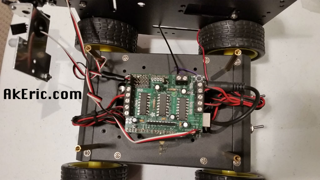
- I had to solder in extra connections to the analog pins on the motorshield to allow fo the Ping))) sensor to passthrough it to the Arduino (acting as a digital pin). However, the motorshield has the pins in the order of “signal\-\+”, while the cables from the Ping))) (and servo) are “signal\+\-“. Not sure why the motorshield would break ordering convention, but I had to splice and re-wire the Ping))) cable to match the board.
- The motorshield docs say that servo2 is pin9, but it’s actually pin10. That took me a while to figure out… :-S
- I ran into a lot of problems with the programming of the robot itself:
- The behavior is to run, ping, scan, repeat. But during “scan” it wouldn’t drive the servo full left\right: Sometimes it would only got left, never make it right.
- To solve this, I put a “timer” in the code, that would only execute the main loop if a certain amount of time in ms had passed (30ms to be exact, which makes it run around 30fps in game terms). This seemed to make it behave exactly how I wanted.
- I thought I needed to tell the motors to run on every loop: It turns out they’re a state machine: once you tell them to run, they keep running until you tell them otherwise. Knowing this helped me clean up the code.
- There doesn’t seem to be any official documentation I could find to the motorshield library, I had to crack open this header file to deduce what it could do: AFMotor.h
Picture time! Click to enlarge:


And a final shot of the wiring on the board per request:
I tried this over and over, and I am new to processing, but I think that it already should have began working.
I keep getting this in the bottom of the processing program:
“WARNING: RXTX Version mismatch
Jar version = RXTX-2.2pre1
native lib Version = RXTX-2.2pre2”
Did I download the wrong program for processing?
Any help would be fantastic!
And thank you for the share.
This uses the Arduino language, not Processing, although the IDE’s look very similar. If you’re using Processing, and not Arduino, that’ would be one problem, since there would be no way to get the data uploaded to the board. If you are actually using Arduino, my guess would be the version of Java on your machine differs from the version of Java that Arduino expects: Maybe uninstall Java, grab the latest version online, and see if that makes it happy? Also, if you Google the above error, there are a lot of posts on it.
Hi,
I was wondering if you could send me the code to this robot plese, also will the code work with a arduino romeo i think it will because arduino romeo is one board its a arduino and a motor shield in one. Any way could you please send me the code and answer my question as soon as possible.By the way nice work on the bot. Sincerely,
Sean
The code is posted above in the post. I’ve not used an Arduino Romeo, but it sounds like an interesting solution.
Can you send me a schematic on how to wire up the motors and ping sensor and batterie also does it change any thing if i connect both left wheels together and both right so it kinda drives like a tank
The schematic is in my head, but if you look at the Arduino sketch it conveys how to plug everything together (via which item is connected to which pin). As far as your other question, I’d ping the adafruit forums, since that’s more specific to the motorshield behavior. But as is it currently tank-steers: That chassis provides no other mechanism for steering.
so can you give me a link to the arduino sketch or is it somewhere on this page
is it ok if i put the ping sensor over the chassis not facing down
You can put it wherever you want, it’s your robot 😉 I hung mine that way so that it was scanning closer to the ground. Originally I had it on top, but it would end up bumping into low obstacles too much. Although the ping docs warn that putting it too close to the floor can screw up the readings.
thanks but when you built the robot do you have the primary bateries hooked to the robot and arduino or do you have the arduino connected to a 9 volt battery seperately
yes, I have the Arduino on a separate 9v.
for somereason when it try to upload the code it says Af motor does not not name a type
does the code AFmotor.h work better then the other code or its not a code because every time i try to uload the code it tells me that AFmotor does not name a type
Sounds like a question for the Adafruit forum.
@AKeric
Nice robot!
The reason the AA battery holder is for five-cells is because it is for 1.2v rechargeable batteries… 5 x 1.2v = 6 volts. The voltage the motors are designed for. The robot kit comes with a charging jack that mounts on one end next to the on/off switch so the batteries can be recharged without disassembling the chassis.
Thanks I have the charging jack hooked up… but based on my experience most rechargeable batteries need some charge-circuitry between them and the power, that can vary depending on the type of rechargeable battery used. This has none, which I find questionable: I don’t think hooking up bunch of rechargeable batteries to a random wall-wart is a good idea.
?
@AKeric
I was thinking more along the lines of a charger designed for 6v NIMH battery packs. http://www.onlybatterypacks.com/showitem.asp?ItemID=11862.12
I have the same mobile platform and servo/ping sensor and was searching the web for ideas when I came across your website. I plan on using a FEZ Domino and .NET Micro. If you don’t mind, I’d like to get some ideas from your Arduino code that you have posted above.
Feel free to use the code, I posted that stuff to share 😉
Looks like that charger may work: Just slap a barrel-jack connector on the end and you’re good to go.
Eric,
Uploading the (your) code successfully. Unfortunately, Robot just stand still and motors does not spin. Ping scan once then stop. PLEASE HELP.
Note: I wire up the motors, servo and ping sensor similiar to the sketch.
I have the Arduino and Motor Shield on a separate power.
Am I download the wrong code?
Thanks
The code I have listed above is the code I used. I’d advise putting a bunch of Serial.print statements in the code to see where things are quitting, that’s basically what I do. As I developed the robot, the code started out very small, and eventually got to where it’s at now: I’d advise breaking it into sections, and making sure you can get each section individual working before trying to get the whole thing to execute… hardware\software at this level is rarely plug-n-play.
I changed the project .pde with my shields and here it is:
http://robotx.ro/download/NAVIGATOR_test.pde
I initiate the motors :
int EN1 = 6;
int EN2 = 5;
int IN1 = 7;
int IN2 = 4;
it acts strange, it does not stop when detecting obstacles 😀
Hallo
I want the 4wd whit the lcd 2 16 , so that I see the distance in cm on the lcd.
please can jou make the programming for dat end send me the code .
The code there for i cant make it plese help me.
can you make a code that will work with arduino romeo and if not then tell me why when i download the program the arduino says something like afmoter not named and then a bunch of numbers please tell me how i can fix it becuase i really dont have much experience with programming
Sorry, you need to write you own code, I have a hard enough time with my own 😉 If you’re still having problems I’d contact their tech-support.
were did you learn to write code for the arduino becuase your code doesn’t work. so maybe i should write my own code. so did you learn off the computer or website
I learned to code Arduino from their web-site, and a variety of books including the Arduino Cookbook. The code I provide is an example that works for that hardware configuration. If your hardware varies, there’s a good chance it won’t work, so yes you’d need to write your own. But that’s the whole point of sharing stuff like this, to provide people the resources they need to expand their own skills. It’s safe to say I had to write all my own code since nothing out there I could find would do what I wanted, let alone for this custom hardware configuration.
@mitch: I downloaded and used AKeric’s code and it worked perfectly. The only thing I adjusted was the centering constant for the servo. I do have the same hardware.
@AKeric: Good job!
ya but when i try to upload it keeps telling me af.motor not named and there like thirty lines of the same thing written over and over in red so i decicded to learn how to write code myself
@mitch: Sounds like maybe you do not have the AFMotor,h file in your arduino IDE. Here’s a link: http://www.ladyada.net/make/mshield/download.html that might help you with installing it.
Hi Eric, this project is awesome. I been working in something very similar, But I’m not sure where or how can I connect my ping sensor to the motor shield. Do you have a picture on how you wired that that you can send to my e-mail?
Thanks in advance.
Jorge Cornejo
There’s an area on one of the corners of the motorshield that have a bunch of holes for you to solder in headers: These correspond to underlying Arduino pins. But their ordering (on my board) is a bit backwards. If you look at the pic of it on this link:
http://www.ladyada.net/make/mshield/
It’s all the holes on the bottom right of the shield correspond to the Arduino’s Analog 0->5 pins.
From my post above, I talk about how the pins were in a different order than the connector cables, but that attached pic has the order fixed… maybe I had an old version of the board and they’ve since fixed it:
“””I had to solder in extra connections to the analog pins on the motorshield to allow fo the Ping))) sensor to passthrough it to the Arduino (acting as a digital pin). However, the motorshield has the pins in the order of “signal\-\+”, while the cables from the Ping))) (and servo) are “signal\+\-”. Not sure why the motorshield would break ordering convention, but I had to splice and re-wire the Ping))) cable to match the board.”””
Awesome.. Thanks a lot….
hey guys thanks for all the help but when i upload the code the robot just sits there and the ping doesnt even blink the active led. i tried numerous times but still it just sits there I NEED HELP
I have the Ultrasonic sensor that has the 4 pin,vcc, gnd, echo, and trgr. How do i make that work with this code?
Hi
I’m a undergrad student and in my last year project, im suppposed to do the same thing for part of my project, so im gonna take a look and get some ideas on how to program it. And thank you, this has been very helpful so far.
cheers!!
😀
Hope it works out for you, it was a fun learning experience for myself 😉
And also i’ve got a follow up question, about the motor sheild.
The data sheet talks about the motors connected to port 3 and 4 can be only run at 1 kHz and just in the next page it says it could be run in other frequencies. and also do we need to use the frequency when giving the speed that it needs to be run since, the pin connected to port 3 is also used by xbee sheild. I wanna know if the frequency is a main factor?
thank you for your time
I’m honestly not sure: I just used example code I found online for driving the motors and it worked. If you look at the example code I posted I pass in this constant as an arg to the motor object: MOTOR12_8KHZ
but presumably there are other ones. Sounds like a good question for the Adafruit forums.
im am sorry if im bothering u, but i’ve got a question.
i want to ask u before i try doing this. is it possible to write a code to measure the distance while the car is moving and not stopping to take distance measurements. Will it be complicated?
thank u!
I don’t see that as being a problem as far as coding it. I coded mine to stop and look, but it could keep moving and look at the same time. I figured it it was moving while looking, it could get stuck: Best to stop, figure out where it should go, then turn that direction, search again, etc.
lol i just found this error in the adafruit motor sheild, servo 1 is connected to pin 10 not pin 9, i was wondering why my code was not working iand i just happen to swap it. lol
and also are you sure that 6V would be enough since the data sheet says ,”You can’t run mo to rs o ff o f a 9V battery so do n’t even waste yo ur time /batteries!”. Just wanted to confirm prior to ordering them.
@Kishan
that was a stupid question, the maximum voltage that my dc motors could run is in 4.5 V just noticed.
How to connect the arduino to the batteries? Since the arduino has only a USB port to connect to a laptop then how to connect to the batteries?
The Arduino (depending on the model) has multiple inputs for power: Mine has USB, a barrel jack, plus Vin pin. I powered the robot over the Vin pin.
http://arduino.cc/en/Main/ArduinoBoardUno
Does motor with 2 screws has to be tightening on chassis?
Nice work! We built a similar project. However, we installed an Android device onto a RC car and used an IOIO board instead to control it autonomously. Here is the preliminary result:
http://youtu.be/vkvkfcqEUkk
That’s pretty slick, a bit more advanced than what I’m doing 😉 I feel like you should put a dog costume on the robot 😉
It can be built with Arduino UNO?
Would the code?
Thank You
I’d expect an Uno to work just fine.