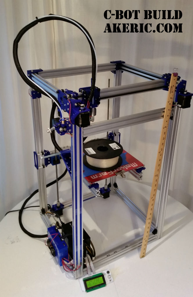
Building the C-Bot 3D printer: Part 17 : Electronic & Software day 2
Jump to C-Bot blog index to see all the posts.
Update: Since authoring this post I have switched my electronics to RADDS, and my firmware to Repetier. See the “Part 31 post” for the latest on it.
After posting my z-stage problems to the C-bot forum, they suggested I try a couple things: Loosen up the bolts on the ACME lead-screw blocks, and switch to using dual motor drivers, rather than one, like I’m currently doing.
I loosened things up, and it helped a negligible amount, but I was still unable to predictably raise the build platform. So, I decided to dig into Marlin and enable dual-z-steppers.
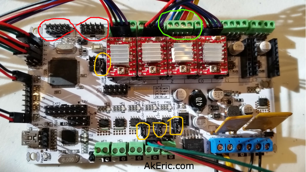
Which I did, and then added an additional A4988 driver to the Rumba board to make use of it:
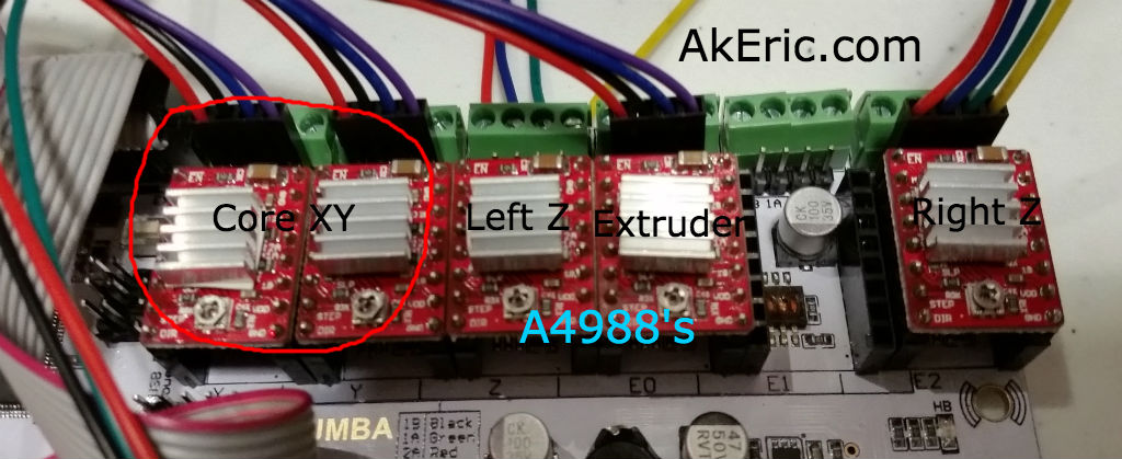
A4988 Drivers, with dual-z support.
I added the additional A4988 to the “Extruder 2” plug (on the far right), plugged the right z-stepper into it, and gave it a go: The steppers would only lower, not raise. NOW what?
Looking at the Marlin code, I noticed that the block I enabled (starting with ‘#define Z_DUAL_STEPPER_DRIVERS’) to support this looked different from the same block in the “Marlin Configurator“: It appeared that it was also enabling “dual z endstops”, which I didn’t want to happen. Rearranging the code resolved this, and now I have a bed that both lowers, AND raises. Finally. I was going to post this code-fix, but I diff’d the Configuration_adv.h file Mason had given me with the one I pulled down from GitHub, and that code section was radically different. I’m not sure which is newer\older. At least mine works now…
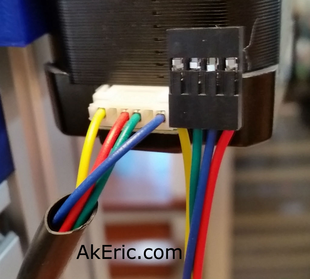
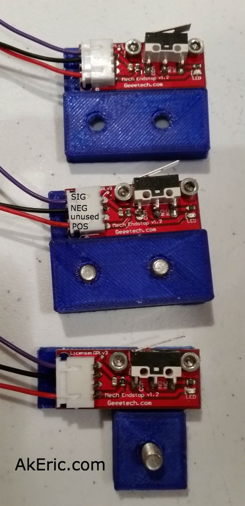
Now that I have the z-stage working, I decided to focus on the endstops: I had mocked them up earlier, but didn’t have them wired properly… at ALL. I spaced out and thought I only needed two wires (+-), but in reality you should also hook up signal, so the LEDs light up. More splicing and crimping ensued, and I got the Geeetech v1.2 endstops wired up correctly, based on this great pic Mason pointed me to…

… living in this thread, that explains it pretty plainly. Thus the end results:
From there, it’s getting them plugged into the Rumba correctly:
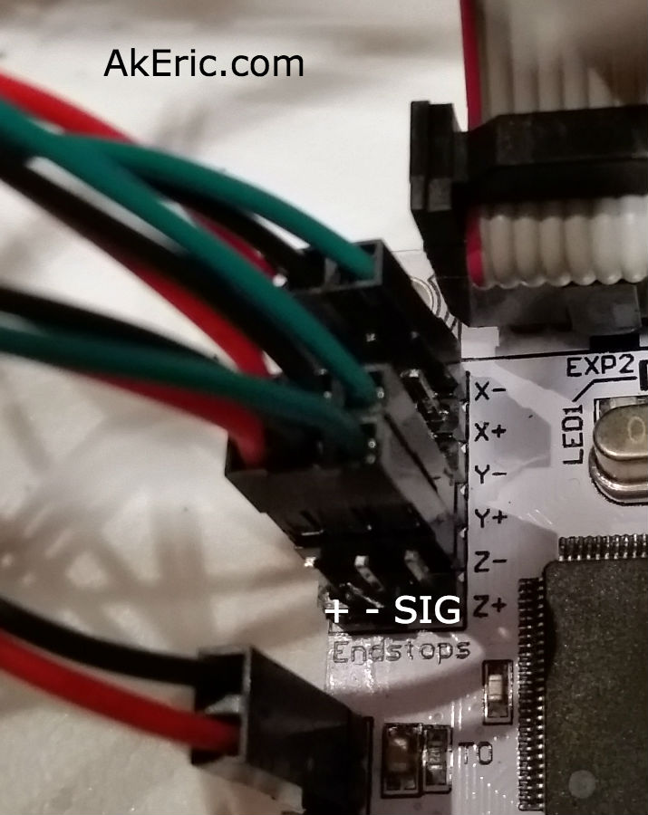
Note: Since I took this pic, I’ve changed my Y endstop so it is now Y-
Here’s the logic behind it:
- Looking down on the build platform, zero XYZ is in the bottom left corner. +X is to the right, +Y is towards the back, and +Z is up.
- The X-endstop is on the left side of the Y-gantry, that the extruder blocks hits when traveling left: It is in the “negative” position, thus X-.
- The Y-endstop is mounted on the top-left-rear corner of the printer, and the Y-gantry hits it when it moves back in a ‘positive’ direction. So it’s Y+.
- Note: Since I authored this page I’ve moved my Y endstop to the top-left-front corner, so it’s really Y- now.
- The Z-endstop is mounted towards the top of the left rear leg of the printer, that the Z-stage hits when it lifts up. Since when the build platform drops it’s going in a ‘positive’ direction (or, instead, imagine the build platform on the bottom of the printer, and the nozzle lifting up instead, which is effectively the same thing), it means it starts at the negative position, thus -Z.
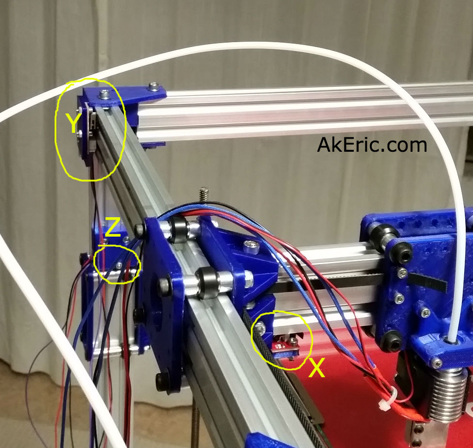
Note: Since I took this pic, I’ve changed my Y endstop so it is now Y-, or on the front-left of the bot, rather than rear-left as in this pic.
Once the endstops were wired up, I was able to ‘auto home’ the whole system from the LCD, and… it worked.
Finally, no more blockers… next up will be calibrating the XYZ travel distances.
Jump to C-Bot blog index to see all the posts.


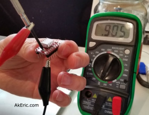 There appear to be a variety of ways of setting the current limit, but a way that Mason used is this : Using alligator clips, connect one lead from your multimeter to the ground pin on the A4988, and the other to a small screwdriver: You can then put the screwdriver in the trimpot and check the resistance : For the A4988, you want to set it to just under 2.5x what the stepper can draw (you can find this formula under the ‘Current Limiting’ section of the A4988 page linked to above). My stepper can draw 1.68A, that divided by 2.5 would be .672, or 672 ohm on my multimeter. Note, after going through all these steps, I learned that the value on the multimeter actually needs to 10x that amount: So I’ll got just a bit under, and set it to 6500 ohm. It should be noted that other stepper drivers have different values. For example, the DRV8825 (what Mason’s using) divides by 2, not 2.5.