It’s been great having two weeks off over the holidays, and a newly assembled X-Carve. Following up on previous posts, this is more learning, saved on the web for my future reference. Current CNC skill level = noob.
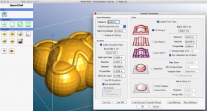
MeshCAM
 While Inventable’s Easel ($ = Free) is great, I’ve quickly exhausted it’s capabilities. Specifically, I want to model 3d objects in Autodesk Maya, and mill them on my X-Carve. Currently Easel does 2D (cutouts) 2.5D (cutouts at multiple heights) but not full 3D objects. Reading the forums there appears to be several popular software packages out there that do what I’m after, two of which include MeshCAM ($250-$500) and VCarve ($350-$700). My issue is I’m on a mac, which is very limiting in the world of CNC as I’ve learned, so I can’t even test V-Carve
  MeshCam it is!
MeshCAM does give you a nice fully featured trial period (couple weeks) to check it out. And it does exactly what I’m after: Creates multi-pass (roughing, finish) toolpaths based on my 3d objects. Pros is that it does that well! Cons is that the UI feels a bit antiquated compared to most 3d software I use, and I can’t really find any robust instructions online (they do email you a tutorial a day once you get the trial though). But it gets the job done.
List of tutorials I’ve found:
Other Links:
And, it exposed the first issue that prompted this whole post: Since it provides for multi-pass cuts (requiring a tool change), how can I actually implement them?
Touchplates
To do a multi-pass cut (as I’ve been learning), you generally use a big fat bit on the roughing pass to remove a bunch of material, then a finer bit on the finish pass to make it look all nice. But this obviously means you need to swap bits. And if you swap bits, how can you guarantee that the Z-height is the exact same on the finish pass as it was on the roughing pass? Since when you remove bitA and add bitB, there’s no way a human can guarantee the tip of bitB is at the exact same location that bitA’s was.
Reading the forums it quickly became apparent that I needed a ‘touchplate’ : A chunk of metal of a known thickness you can use to effectively ‘close a circuit’ with the spindle bit: When that circuit is closed, you know you’ve hit the top of the material you’re about to mill (with the bit a known distance above it).
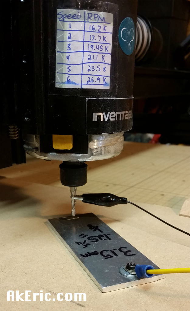
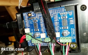
I fashioned my touch-plate out of a scrap of 1/8″ aluminum my father had given me from a previous boat build: Drilled a small hole in one end, affixed a wire to it through a bolt tapped into it.
From there, per the forums, I connected that to the Arduino Uno’s A5 pin, and another wire with an alligator clip on the end to it to the gShield’s ground. The main issue is the analog headers on the Arduino are hard to get at because of the gShield on top, but I was able to get a small lead plugged in (see below image).
But once it was all wired up, how to test, and ultimately use?
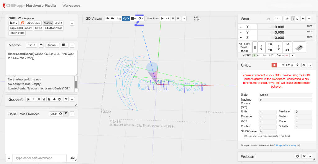
ChiliPeppr
ChiliPeppr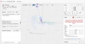 is something I only recently learned about: A tool for sending gcode to your device, supporting tinyG and Grbl (which the X-Carve uses), and ‘generic serial’. The Universal GcodeSender (Grbl only?) was a close second (and I got it up and running, which required a frustrating update of Java on my mac), but honestly ChiliPeppr just looks cool while you’re using it. While Easel allows you to send gcode to the gShield, I couldn’t actually get it to execute the (below) touchplate gcode: The machine would just make a weird vibrating sound. Could be my complete lack of knowledge on the subject, and I wanted to learn how to use ChiliPeppr anyway.
The first stumbling block was figuring out how to connect ChiliPeppr to my X-Carve (since there are no instructions for ‘first time users’ I could find) : As it turns out, based on the smallish screen of my Macbook Air, the menu on the bottom right that lets you “Download Serial Port JSON sever” wasn’t visible. You need to install and run that server (a shell pops up to let you know its running) to allow ChiliPeppr to talk to the X-Carve. Once that was done, I was in business.
One thing I’ve noted about ChiliPeppr every time I’ve used it to make a cut (total of three times now) : It seems to randomly pause. I have to “unpause” it, and it happily goes along it’s way. Not sure what is causing this, nor can I find any errors/warnings shown.
Other ChiliPeppr links:
Multi-Pass Cuts
Being the CNC noob that I am, since I couldn’t find any docs for this (meaning, using a combo of MeshCAM, Chilipeppr, and doing multi-pass, tool-changing cuts) anywhere. So below is a rough outline of my experience doing just that:
- In MeshCAM I created both a rough and finishing pass, and saved out the gcode using the “Shapeoko GRBL-Inch” postprocessor.
- I drag & dropped that .nc file into ChiliPeppr.
- In ChiliPeppr, I used the jog controls to move my toolhead to the bottom-left corner of where I wanted the cut to start.
- Using the touchplate, I put it under the toolhead, connected the alligator-clip to the it, then created a ChiliPeppr JavaScript macro:
- macro.sendSerial(“G20\n G92 Z0\n G38.2 Z-.5 F1\n G92 Z.124\n G0 z.25”);
- The above (modified) code is thanks to a X-Carve forum post by user CharleyThomas. The raw code on a single line looks like:
- G20; G92 Z0; G38.2 Z-.5 F1; G92 Z.124; G0 z.25
- G20 : set to inches
- G92 Z0 : Zero the Z axis, I added this later: Before I added this, there was a bug that the first time I’d run the macro, the toolhead would go up, not down. There was some speculation that since the coordinate system wasn’t set yet, the machine thought the toolhead was too low, and would auto-raise it. Regardless of the issue, this command solved it.
- G38.2 Z-.5 F1 : Move the spindle down half an inch max looking for the touchplate
- G92 Z.124 : Set the z-height to the thickness of the touchplate (mine is .124″)
- G0 z.25 : Raise the spindle to 1/4″ above the material.
- Note, as I was authoring this, I realized ChiliPeppr has a ‘Touch Plate’ widget, but I have yet to investigate it.
- From there I turned on the spindle, and fired off the gcode.
- When it paused for toolchange, I swapped the bit, then re-executed the above steps with the touchplate and macro to re-zero the z-height. Then unpaused it to continue the work.
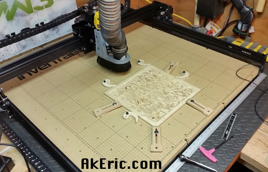
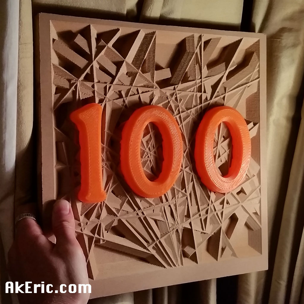
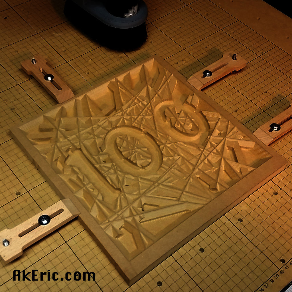
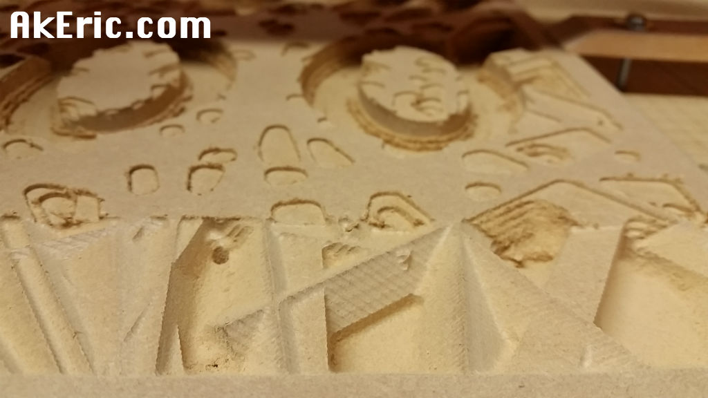
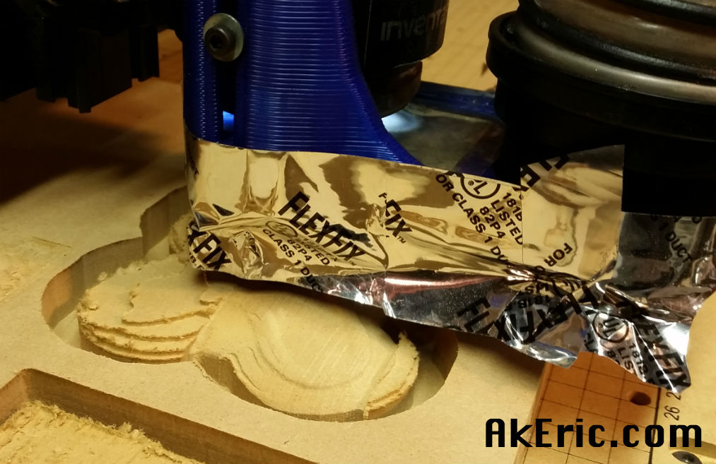
Worked like a charm:
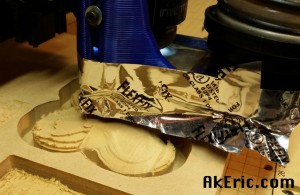
In the above pic you can see the finish pass emerge from the rough.
All in all, a pretty rewarding experience.