Posts Tagged ‘ Maya

New 3D Print: Maui

I’ve 3d printed a few other maps, and got a lot of enjoyment out of it:

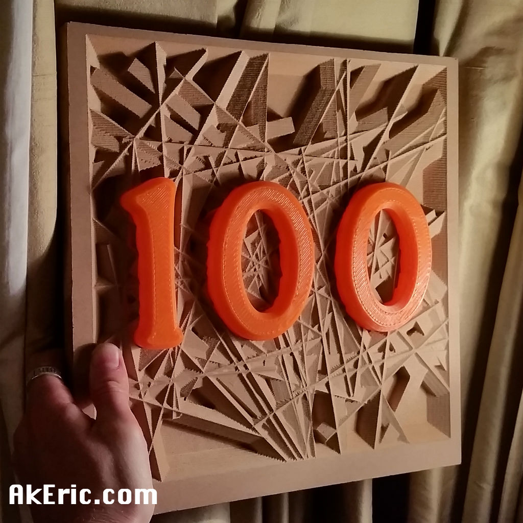
I recently spent a week in Maui:  This gave me inspiration to do a (painted) 3d print of it on my C-Bot:

maui_painted_main

The below post is an overview of how I designed, printed, and painted it.


Getting the Mesh Data

I first headed to the web app Terrain2STL : This is the great little program that lets you download 3d-printable terrain data.

However, no matter what you set the capture-box size to, it captures the same resolution of data.  If you make the box the size of the whole island of Maui, you end up with a pretty low-resolution capture mesh, based on the detail I want to 3d print.  So the only way to get a ‘high-res’ Maui mesh is to download many small chunks, that will later be seamed together to build a high-res island.

In Terrain2STL, I set the box size (ARC seconds) to 360.  Based on that size, I can adjust the latitude & longitude values by .1 values, to offset the box by one length in either direction.  So stating at the NW corner of Maui, I started capturing squares of it’s mesh.  In total, I made 30 captures.

Assembling the Mesh Data

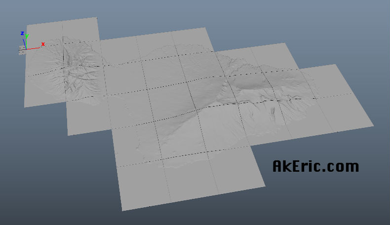
In Autodesk Maya, I created a new scene, and started importing in each STL that Terrain2STL generated.  Starting in the NW corner, I’d import in the next stl, line it up with the last, and repeat that process.  Which gave me something that looked like this upon completion:

maui_maya_chunks_raw

I then went through the process of deleting all the mesh that wasn’t part of the island, stretching all the edges down to make a cliff-like effect, making a base for it, and creating the text.  I also did a lot of mesh cleanup since the Terrain2STL tool isn’t perfect.  Final Maya result:

maui_maya_final

tried to boolean all the mesh together, but Maya just wouldn’t do it.  This left me frustrated, but I realized that Simplify3D (the slicer I use) allows you to import in multiple mesh:  In Maya, I made sure the pivots of all the mesh were at the origin (so they’d all show up in Simplify3D in the correct location), the transformations frozen, and I exported every individual piece as a new STL.

Slicing The Data

I imported all the stl’s into Simplify3D:  They appeared to all line up correctly.  I wanted the island to be scaled 2x on the Z axis, so I grouped all that mesh, and applied the scale transformation.

But when I sliced it, I noticed lots of little gaps between the mesh chunks:

maui_sliced

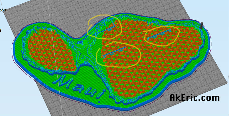
Come to find out, even though all the mesh was lined up correctly, in some cases… it just wasn’t enough for Simplify3D : This spawned a painful process of me moving pieces, re-slicing, checking gaps, etc.  But eventually I got rid of them all.  The general prints stats were:

  • 200 micron, .4mm E3D-v6 Volcano nozzle
  • Maker Geeks Gray’matter Gray PLA @ @210 deg.  Bed @ 50 deg.
  • 90 mm\sec print speed.
  • 2 shells, 4 roof\floor. 10% ‘fast hexagonal’ infill.

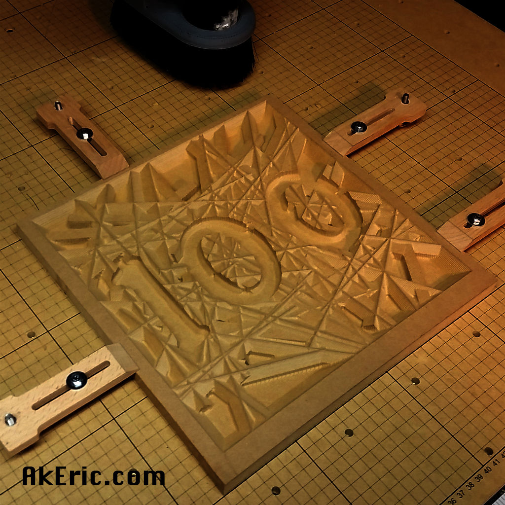
Took around 13 hours to complete.  Based on my 12″x12″ build platform, printed diagonally it came out to 14″ across:

maui_noPaint

Painting the model

I wanted to try a new (for me) dry-brush technique to show off the mountains.

To start, I shot the whole model in a pleasing Rust-Oleum ‘Meadow Green’ color:

maui_midPaint

After that dried, I sprayed “Maui Blue” (can’t believe I found a color that matches the medium I’m painting) onto a foam brush, and painted up the ocean.  Finally, I sprayed a light-brown onto a paper towel, and then brushed it across the mountain peaks for the final result.

maui_painted_NW maui_painted_SW

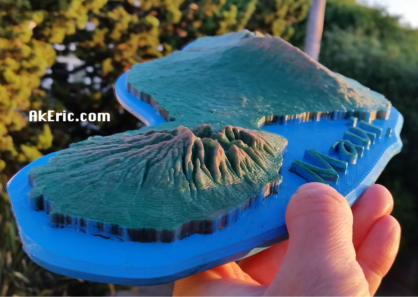
Was really pleased with the results!

New X-Carve project: Soap Dish

Working with the X-Carve has been a lot of fun.  A while back I 3d printed the “Soap Holder by piuLAB“, and figured something similar would be great to route.

Took some time in Maya generating a pleasing voronoi pattern for the top of my soap dish, which I cut out of alder, and the bottom out of some red oak:

soap_wip

Generated the gcode in MeshCAM, and use Chilipeppr to send it to the X-Carve.  Still a lot of learning:

  • For the top:
    • Used a 1/8″ 1-flute upcut endmill at 120″/min, 1/16″doc, 1/16″ stepover, Dewalt611 at 1.5, based on chipload calculators.  It seemed to cut just fine. but as you can see (if you zoom in) there is vertical banding on the Z.  After posting to the forums, the consensus is I’m cutting too fast.  So… I’ll slow it down next time 😉
    • It didn’t cut all the way though, so I had to use an x-acto to cut out the rest of the pockets.  Either I need to trick it into thinking my material is thicker, or do more tuning on my Z-steps.
  • For the bottom:
    • Used a 1/4″ 1-flute upcut endmill at 120″/min, 1/8″doc, 1/8″ stepover, Dewalt611 at about 2, based on chipload calculators.  It seemed to cut just find as well using a conventional climb cut on the rough pass, but on certain sections I got a lot of chugging.  Again, too fast.  Slower next time.

When it was done I applied some stain to the top, and sealant to both, and came up with this:

soap_final

Not too bad all things considered :)

You can download the STL’s from Thingiverse here for routing, or 3d printing.

Digital to wood : A new X-carve piece

New piece I made on the X-Carve:  It measures just under 12″ square, by 1/3″ thick, birch plywood, with some ‘natural’ stain applied:

final_piece

So how did I get there?

Years ago, like ’98-2000-ish, I was really into building shader networks in Maya.  I loved their ramp shader, so versatile.  Later Maya introduced their ‘layered shader’, which is a lot like a layered file in Photoshop.  Over the years my career in CG has taken me away from shader creation, but I always remember how much fun it was ‘back in the day’.

Fast forward to now with the X-Carve :  I know that I can turn a grayscale height-field into mesh, and MeshCAM will turn it into a toolpath, so this was my first attempt at doing just that, via a shader network in Maya:

shader_network

This visualizes (from right to left) the shading group (which the mesh is assigned to) that has both a lambert (just for mesh visualization) and displacement material (for later conversion to displaced polys) assigned.  They’re in turn both fed by a layered texture, that has inputs from a ramp (on top) that defines the border, an ocean texture (that makes the ripples), and another ramp that makes the circles.  I authored a Python script that automates this whole creation process and mesh assignment, with a simple window so I can repeat this process easily.  Iteration is king.

From there, I had something that looked like this, assigned to a flat, tessellated polygonal plane:

heightField

Which I then converted into displaced polygons (Maya: Modify -> Convert ->  Displacement To Polygons)

polygons

Exported as an stl, and brought that into MeshCAM for toolpath generation as a two-part cut:

  • Rough pass with a 1/4″ two-flute upcut endmill.
    • 60 inch/min
    • DOC .0625″
    • Stepover .125″
  • Finish pass with a 1/8″ two-flute upcut ballnose.
    • 60 inch/min
    • DOC .0312″
    • Stepover .025″ : Should have doubled this to get rid of the scalloping.
  • Had the DeWalt 611 router speed set to 1 on both based on rough chipload calculators:  Seemed to do fine, occasionally had some stuttering on the rough pass.

I sent the gcode to the X-Carve via Chilipeppr, and over the next 2.5 hours watched the magic ensue:

finish_pass

The above pic shows the final pass emerging from the rough.

Until the final product appeared:

route_complete

All the hold-downs are overkill, but I realized I had told MesCAM to machine the entire stock, so I had to move them around as the progressed from bottom to top, or I would have machined the clamps themselves.  Noob move.

Pretty happy with the end-result:  It’s actually quite confusing to the eye in person as the shadows dance around it.  Great test though, and a lot learned.

Making The OneHundred

I always found it, humorous, when some Instagrammer got ‘X number’ of people and made some crazy post about it:  “LOVE you all, hugs and kisses”, etc.  I recently hit 100, and figured this would give me a good excuse to combine both my 3d-printing and newfound CNC-routing skills:

I’ve been wanting to do a piece that combined both 3d printing and CNC routing, some came up with idea of a routed background, with 3d printed text.  “The OneHundred” was thus created:

beautyShot

Info on the techniques used to make it:

3D Modeling

The model was created in Autodesk Maya:  I wrote a super simple tool to randomize the rotation and position of simple poly cubes that made up the background.  A 3d model of the text was generated, and Booleaned out of the background.  An stl was generated for both the background, and the text.  The piece is 12″ square, by 3/4″ deep.

3D Printing

The text model was sliced using Simplify3D, and printed on my C-Bot directly off the SD card (I recently was printing something via Octoprint, bumped the RaspberryPi, and it lost USB connection half way through a multi-hour print… don’t like that at all).  Settings:

  • Filament: Makergeeks Orange PLA
  • Extruded @ 230deg (hot for PLA, but per manufacturer recommendation), bed @ 60 deg
  • 1.2mm E3D-v6 Volcano nozzle
  • 600 micron layer heights, 1 shell, 20% fast hexagon infill.
  • Print speed is 45 mm/sec : Sounds slow, but that’s a volume of 32.4 mm3/sec extruded.  For those keeping score, a the volume extruded of a .4mm nozzle with 200 micron layer heights at 90mm/sec is 7.2 mm3/sec:  Volcano is printing 4.5x as fast, crazy.
  • Took about 1.5 hours.  (so, based on the above specs, it would have taken 6.75 hours on a ‘normal’ printer).

CNC-Routing

MeshCAM was used to generate the toolpath cut from the MDF background.  The gcode was sent via the Chilipeppr GRBL workspace.  MeshCAM settings:

  • Roughcut:
    • 1/4″ 2 flute upcut endmill
    • DOC: .0625″
    • Stepover: .125″
    • Feedrate: 60″/minute
    • Took about 1.25 hrs
  • Finish Pass:
    • 1/8″ 2 flute upcut ballnose
    • DOC: .0312″
    • Stepover: .025″
    • Feedrate 60″/minute
    • Took about 3.25 hours

The above settings are completely based on previous trial and error, and could be improved no doubt.  Things I noticed while cutting:

  • Got some chatter on the roughcut, even when I turned up my DeWalt 611 speed all the way.  Guess I was cutting to aggressive.
  • The final piece has more scalloping than I’d like:  Think I need to lessen the stepover next time.
  • Having to babysit the machine for 4.5 hours was… not fun.  But I got to read some magazines I needed to catch up on.

Final Thoughts:

Great learning experience, I’m really getting the two-cut process down using my touchplate.  Can’t wait to do more!

Exporting usable CAD data from Maya

It’s that time of year again:  Time to help my father build a new aluminum boat.  It was an enjoyable process last year:  Based on a napkin sketch with some dimensions and angles he gave me, I modeled a boat out of NURBS in Maya, and through a lot of hoop-jumping, got him some useable data:

The biggest hurdle was getting him ‘the usable data’. The process of making the boat in Maya is discussed above.  But these were the export steps:

  • Export the mesh from Maya as obj.
  • Use online converter to go from obj -> pdf.
  • Then, my father gave the pdf to a buddy who traced it in CAD, gave it dimensions, then provided that to the plasma-cutter (as a DWG).
  • Ugh.

That process was super clunky.  I’ve been using Maya since… 1998(?) and never once needed to export anything CAD related, so this was all new territory.  To make this work I need a way to generate the CAD data myself, add dimensions to it, and export out as a DWG.  There must be a better way!

Turns out there is (and probably even a super-moar-better way than what I’m about to describe, if you know CAD better than I do, which wouldn’t be much of a stretch).  In the back of my head I remembered that Maya has a DXF exporter.  I don’t think I’ve ever once used it…

Part 1: Get CAD Software & Configure

Since this process is (currently) a once-a-year thing, I didn’t want to drop a bunch of cash (any really) to get some newfangled CAD software.  I’d read a lot about FreeCAD on the interwebs, it was available for Mac, so I installed it.

Fumbling around however, I realized it neither could import DXF, or export DWG, by default.

To get the DXF importer\exporter working, I followed the instructions here.

I never could actually get the DWG export working from the software, even following the instructions here.  However, that links to a standalone “Teigha File Converter” that will batch convert a directory of DXF files to DWG.  Good enough.

Also, this data needed to be in inches, so I changed the FreeCAD prefs as such.

Part 2: Export usable CAD data from Maya

I started by exporting the unrolled mesh as DXF from Maya:  There are zero options available.  But FreeCAD happily imported it.  Immediately, problems:  Missing triangles (you must exported triangulated mesh, can’t have quads\n-gons).  As a check, I exported this same data out as DXF, and reimported it:  Empty.  I don’t think FreeCAD likes to deal with polygonal mesh.

Next, I tried exporting the unrolled NURBS surfaces as DXF:  Those came in as empty groups in FreeCAD…

Finally, I converted the trimmed NURBS to their perimeter curves, and exported the curves:  Success!  This is what is important to know:

Export NURBS Curves from Maya as usable CAD data.

Polygonal Mesh = highly questionable.  NURBS Surfaces = no go.  Note I also tested locators & ‘distanceDimShape’ nodes:  They don’t export at all.

Once I had the boat’s unrolled\flattened curves in FreeCAD, I started adding draft dimensions.  Where I encountered my next problems:

  1. The scale was off by a factor of 10:  Even though Maya was set to inches, and FreeCAD was set to inches, everything was 10x as small in FreeCAD.  I noticed this is the same issue when I 3d print in cm:  Even though I have Maya in cm, and my slicer (Simplify3D) is in cm, they come in 10x smaller.  The fix?  Scale everything up in Maya 10x before export.
  2. From the top view in FreeCAD, all the curves looked just like Maya.  But when I went into a perspective view, the curves were actually going shooting up & down in space quite a bit:  Not on a flat plane.  But they are in a flat plane in Maya.  What’s going on?  Long story short:  In Maya after you do the 10x scale up, be sure to ‘freeze transformations’ on all the curves.  In addition to the scale, I had many other translate and rotate values on the curves to get them flat on the ground plate.  It appears that FreeCAD hates this.  But once everything was frozen, the curves showed up a-ok, from all angles.

Note:  Maya uses the Autodesk ‘DirectConnect’ file translators to export (and import) DXF data.  See the docs on the 2016 version in this pdf.

Part 3 : Add Draft Dimensions

Since I was told that this needed to be provided to the plasma cutter in inches, in FreeCAD’s ‘General -> Units’ prefs, I’d set them to “US customary (in/lb)”.  Next, via FreeCAD’s ‘Draft’ toolbox, I used the ‘Dimension’ tool to provide width & height values for all the curves.  This is where I ran into the next (and as of this authoring, unresolved) issue:  FreeCAD seems to auto-change the what unit is displayed in the dimension based on the length of the part being measured.  For example, I want all the dimensions to be in inches.  But they’d report inches, feet, and yards, depending on the length of the part.  After posting this issue to the forums, I learned that if you switch the units to “Imperial decimal (in\lb)” the dimensions will always be in inch.  Problem solved.  Thanks forum peoples!

Part 4 : Export

From FreeCAD, I export all the curves and dimensions as DXF, then using the Teigha File Converter, convert that to DWG.

And…. done?  Still need confirm from the plasma cutter the DWG is valid (I have no way of testing myself), but overall, a far less clunky data-export-pipeline than last time :)