Building the C-Bot 3D printer: Part 30 : Switching from Bowden to Direct Drive
Jump to C-Bot blog index to see all the posts.
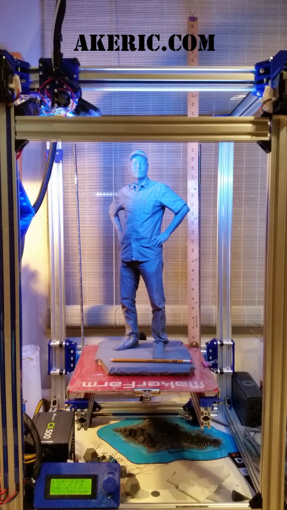
The original design for the C-Bot by Carl Feniak had the printer setup with a Bowden extruder: The stepper pushing the filament to the hotend sat off to the side of the printer, thus removing mass from the XY/hotend gantry: The idea is that if there is less moving mass, you can print faster with fewer artifacts (like “ringing” or “ghosting”). For comparison, my Makerbot Replicator1 (or say, an Ultimaker) is ‘direct-drive’: Its extruder sits directly on the XY gantry pulling filament into the hotend. This is what I had experience with when I started building the C-Bot, but the idea of learning something new (the Bowden setup) was interesting to me, so I went with it.
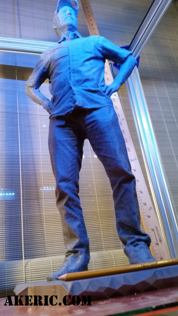
Fast-forward to now: Not a fan of the Bowden setup, at least when used within the specs of my printer design: I have a E3D-v6 Volcano nozzle (I’ve used .6mm & 1.0mm nozzles) on my bot, and that coupled with the Bowden design have had some quality issues I’ve been unable to overcome despite hours (days…) of test printing. Specifically “blobs\zits” & stringing. My guess is, simply too much pressure builds up in the (long) Bowden tube during an extrude move, so when the print goes to do a retraction, a blob still shoots out and gums-up the print, or strings out during movement. Have not been happy with this behavior, and have been unable to remove it entirely. Have greatly reduced it, but it’s always there… lurking…
And during this tuning process I came to the realization that a Bowden doesn’t really help things when you’re using a Volcano nozzle: The benefit of the Bowden, again, is that it removes moving mass from the hotend, allowing you to print at faster speeds. But with a Volcano, you actually end up printing at much lower speeds, just a greatly increased volume\flowrate. Here’s some maths:
- My Replicator1, with a .4mm nozzle, printing at 200 microns (‘medium res’ for that nozzle), at 120mm/sec, has a flowrate of 9.6 mm3/sec (mm cubed/sec).
- The C-Bot, with a 1mm Volcano nozzle, printing at 500 microns (‘medium res’ for that nozzle) at 45mm/sec has a flowrate of 22.5 mm3/sec.
The C-bot printing at a little over 1/3 the speed of the Rep1, but over 2x faster print times overall (based on the flowrate). And when you’re printing that slow, I personally don’t feel the moving mass has such a big effect.
On the flipside, if you’re building one of these bots and running a .4mm nozzle, the Bowden is probably ok: Smaller nozzle, less pressure, less blobs & stringing. But since I’ve never actually used one on my bot, this is only a guess.
Time goes by…
After some discussion on the Forms (starting on this page, where you can also find the files for download, and my detailed comments on its design), Carl created a new “beta” direct-drive system. Which is just amazing of him to do, so again, many thanks Carl! I printed them out on my rep1, spent an afternoon installing them, and what a difference!
-
- Direct-drive, no stringing

-
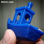
- 3dBenchy hot off the printer

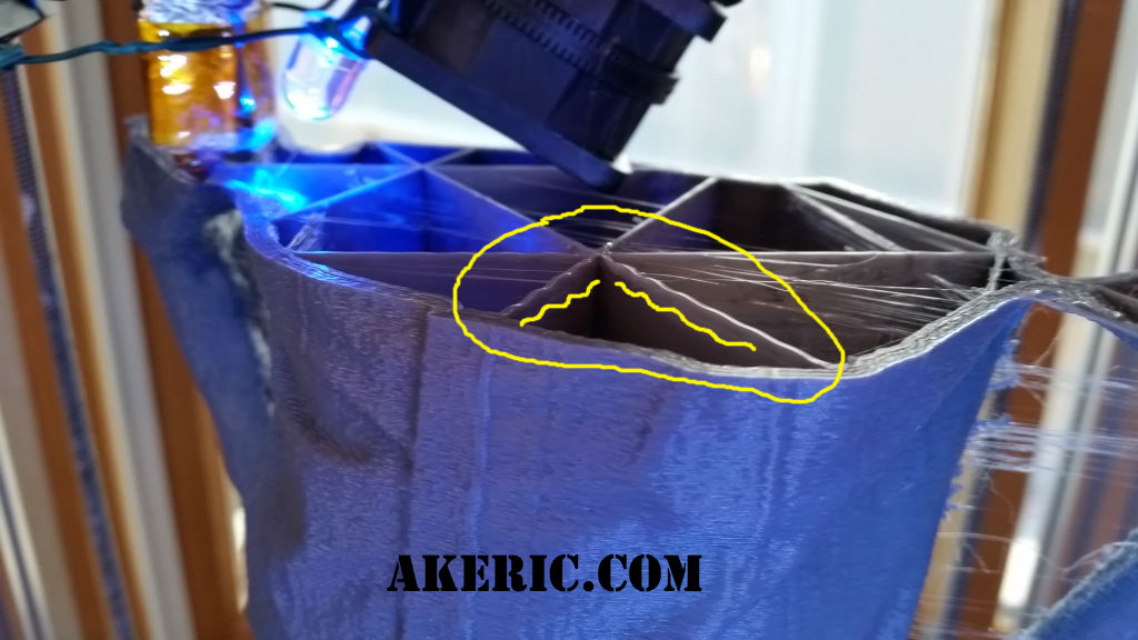
The firs pic shows off the new direct-drive design, and a calibration print of two cylinders: Zero stringing between them. With the Bowden, it would look like a spider could live in there.
The 2nd print is of a 3dBenchy, with no cleanup: Almost no stringing or blobs. Both prints used the .6mm Volcano nozzle.
For both of these, I’m using the same Simplify3D profiles as before, I just dropped the retraction from the 5ish-mm to 1mm. So much more accurate! Currently in the process of tuning them even more.
I also modified the rear-plate to accept the 40mm fan mount & duct as designed by trublu832 on OpenBuilds, and you can find his files here on Thingiverse: No more dual fans, just one ducted one.
As of this post, Carl has released a new version of the parts I have yet to print, but I plan to soon.
But overall, if you plan to build one of these printers and use an Volcano nozzle, I’d highly recommend using this new hotend design.
Jump to C-Bot blog index to see all the posts.