Jump to C-Bot blog index to see all the posts.
This post could also be called:
How the C-Bot experienced catastrophic failure, and survived
The short version of what led up to this point is:
- Decided to print a 3d quad-copter frame on the C-Bot, but needed to swap to my .6mm nozzle from the 1.2mm one that I had installed.
- The last time I used the .6mm nozzle and removed it, I burned out the filament with my butane torch, so it’d be clean for next usage. However, I was a dummy and gripped the threads with my pliers. Even gripping lightly, it marred the threads, compounded by the extreme heat of the burnout.
- When I threaded in the .6mm nozzle, I encountered resistance I didn’t expect. So I just ‘twisted a little harder’, and popped the head off the nozzle. It’s now stuck in my hotblock.
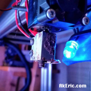 Sad, so sad…
- Ordered a new hotblock, and a .4mm nozzle at the same time: Why not, I’d never tried a .4mm nozzle on the C-bot before.
- Got the new hotblock and .4mm nozzle installed. But when printing at 90mm\sec with Marlin, I got a lot of stuttering, even when printing directly over SD.
- It was suggested I drop the microstepping of my DRV8825’s to 1/16 from 1/32 : This will halve the number of instructions the machine needs to process.
- Pulled the drivers out of the Rumba, flipped the dip switches, plugged them back in, and turned on the machine: Terrible squealing sound, bad smells, etc. Turned it off immediately, but the damage was done: Rumba dead. Even though I double-checked, I had plugged one of the drivers in one-pin off. Magic smoke = released.
- Now I need an all new mainbord. After much research, I decided on a Arduino Due/RADDS combo, running Repetier: I liked the idea of the 32-bit system, and a new firmware that was wasn’t Marlin. Plus if I didn’t like Repetier I can always swap to RepRap Firmware.
So that’s what this post is about: Swapping out my old Rumba for a new Due/RADDS combo, and installing Repetier on it. I’ve made it so verbose mainly for myself, as reference in the future. It is definitely a living document that will be updated over time.
The final product looks pretty slick:
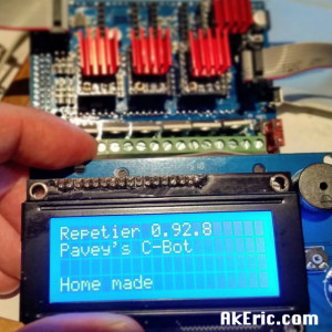
(I do have a fully 3d-printed case for them both now, I just like that pic…)
Installation Notes
My notes below are in the order I performed them to do the swap from my existing hardware. Prettymuch the same order you’d do it in if you were doing this new, from scratch.
After I did my upgrade, I also found this great setup guide: http://reprap.me/media/manuals/RADDS_UserGuide_V2_reprapme.pdf
My development environment:
- OSX 10.10.5
- Arduino IDE 1.6.4
- Repetier 0.92.5
- RADDS 1.5
Hardware Sources:
- Arduino Due : I got mine via an Amazon Prime special for $15.
- RADDS : $61, via MakerFarm.
- LCD : $37, via MakerFarm.
- SD6128 Drivers: 4x, $11.50, via Panucatt.
- Note, there are other stepper driver options out there. One of which is the RAPS128. From the forums, it sounds like there are reason to not get this driver because of it’s ‘inverted’ state (compared to the SD6128). Discussed below in the watchdog section below.
Configuring Arduino Due with the Arduino IDE:
- The Due wasn’t recognized by Arduino software:
- Arduino -> Tools -> Board -> Board Manager -> Search for SAM -> Choose the one that supports Arduino Due
- https://www.arduino.cc/en/Guide/Cores
- Got this error on simple “blink” sketch:
- arm-none-eabi-gcc: error: core/syscalls_sam3.c.o: No such file or directory
- Forums to the rescue > I downgraded the core to 1.6.4, and could then upload.
- Be sure to use the ‘programming USB port’ (the closest one to the barrel jack) to upload sketches to it, I didn’t have success with the other one (‘native USB’).
- Set stepper driver microstepping first, on the back of the board.
- I’m using SD6128 drivers, set to 1/32 microstepping, so it’s {on,off,on}. By default they were {on,on,on} (1/128 microstepping), so I just flipped the middle switch. Based my my query to the forums, the though was presented that humans can’t see much past 1/16, and the higher the microstepping the less holding torque the steppers had. Since I’d previously had my DRV8825’s set to 1/32 on the Rumba, I kept this the same on the SD6128’s. This had the benefit below of being able to use the exact same steps/mm for the steppers in Repetier as Marlin.
- Insert stepper drivers, making sure DIR pin on driver lines up with DIR pin on board.
- Squish the RADDS Shield into the Due. Carefully.
- Connect via the diagram in the link.
- Can’t use a RepRapDiscount display I have on my Rumba board, gotta use the special RADDS display.
Installing Firmware: Repetier
- Instructions via the RADDS page I followed here.
- For future note: A list of all valid G & M codes for Repetier can be found on it’s GitHub page for Repetier.ino : I’ve found other spots on the web that list them (including the RepRapWiki and ironically the Repetier Firmware GitHub Wiki) which all seem out of date when it comes to Repetier’s codebase.
- First step is to go to the Repetier firmware download page, which links to the web-based ‘Repetier Firmware Configuration Tool’ discussed below. After you’re doing configuring, you download.
- Note, Repetier makes it super easy to do a later update: After the initial full download and install of Repetier via the Arduino IDE (info below), to do an update all you have to do is upload your existing configuration.h to the web-based ‘Configuration Tool’, update the settings, then re-download just the configuration.h, which you can re-update via the Arduino IDE. Pretty slick.
- Also note that after you do the first install, some values are only adjustable via the EEPROM (see notes below) unless you disable that feature (See ‘General Tab’ below).
- Repetier Firmware Configuration Tool v092 initial settings:
- General Tab:
- Set correct Processor : Arduino Due based boards)
- Set correct Motherboard : Arduino Due with RADDS
- Set the printer type. Mine is set to “z axis + H-gantry/core-XY (x_motor = x+y, y_motor = x-y)” : I have my “X-stepper” mounted to the top-left, and the “Y-stepper” mounted to the top-right.
- Set the dimensions correctly.
- Set the EEPROM usage.
- By default it’s set to “Set 1”, which means after the initial install of Repetier, certain values are only editable via the EEPROM (via the RADDS LCD). Took me a while to figure this out, couldn’t figure out why changing values (like steppers steps/mm) wouldn’t update when I’d re-upload the firmware: This is the reason.
- Note: Every time you use the configuration tool, if you change this value (from 1 to 2, then back to 1, etc), it will refresh the EEPROM. So if you want to blast your EEPROM values based on some future config, just tick this value from 1 to 2, or 2 to 1 depending on its current state. Actually pretty slick way to do things once you figure it out…
- Mechanics Tab:
- If you’er using RAPS128 drivers (I am not, I’m using SD6128), be sure to check ‘Invert Enable Signal’. See notes on the watchdog section below as to why this could be a bad thing.
- Don’t forget to double your steps per mm (if you’re setting them here now) for the X & Y, since Repetier requires them to be doubled for core-xy machines for some reason (told they’re working on a future fix for that). I plugged in the past ones from Marlin as a starting point, since I was using 1/32 microstepping on that as well (399.486, 401.083, 804.91) – those are the doubled x&y vals.
- If you’re driving both Z-steppers from two different stepper drivers, you can enable that in the ‘z stepper motor’ section. To start, I’m going to try to drive both steppers off the same driver, since the RADDS board specifically has pinouts for that.
- Set “Delay Stepper High Signal” to 1, since this is a Due board. Also read this is needed for core-xy machines. Note I’ve used both 0 & 1 values, and have noticed no difference in print quality.
- Set ‘Move Cache Size’ from 16 (default) to 32 (since we have a lot more memory on the Due than a normal Arduino).
- Set your endstop homing order. Mine is X,Y,Z: I want to get the gantry out of the way of the build platform just in case…
- Set your endstop switch type: Since I’m re-using the “makerbot style” (or RAMPS 1.4 style) mechanical endstops, I set mine to “normally-open”. See ‘Endstops’ below.
- Tools Tab:
- Set the Temperature Sensor for your extruder.
- My E3D-v6 Volcano stated it came with a “100K Semitec 104GT2 NTC thermistor” : This wasn’t listed in Repetier.
- The E3D Troubleshooting docs said: “Repetier Firmware use thermistor definition number 8”:
- #define EXT0_TEMPSENSOR_TYPE 8
- There is no option for that number in the firwmare setup wizard (it’s all by name), but I later set it to that value in the configuration.h file directly via the Arduino IDE.
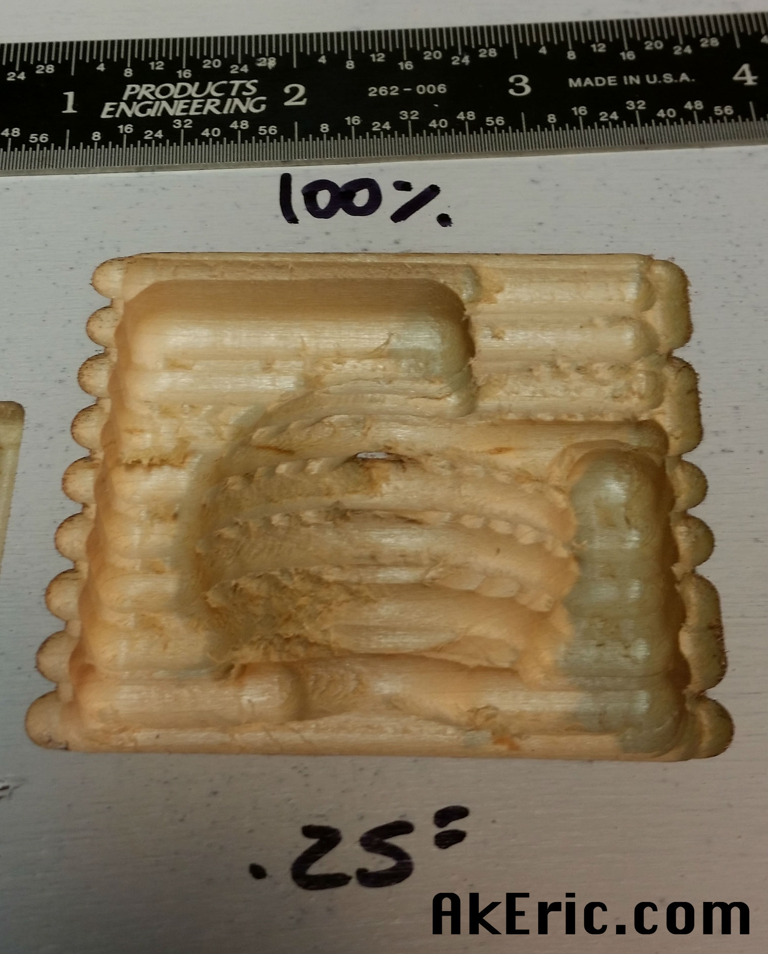
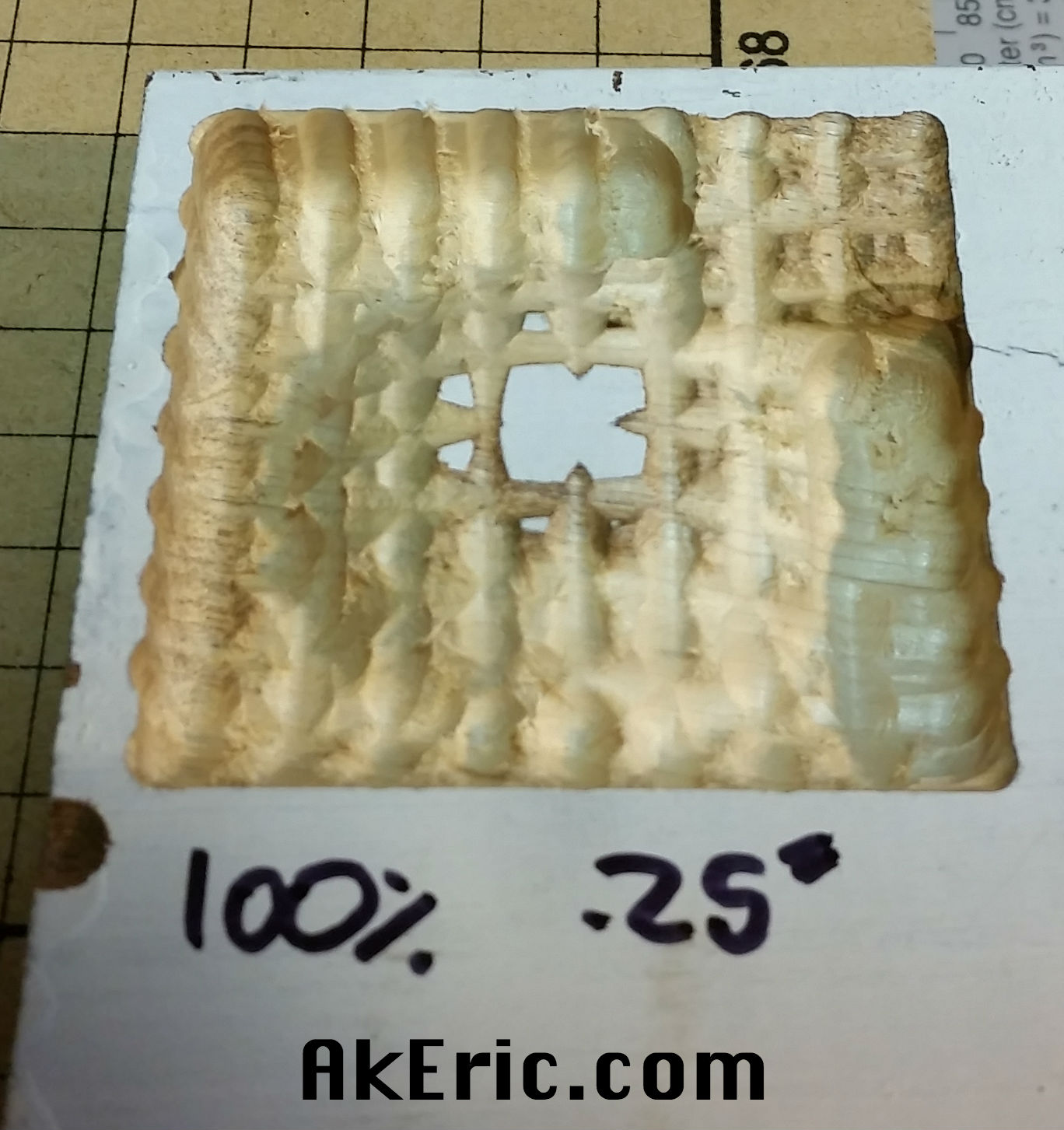
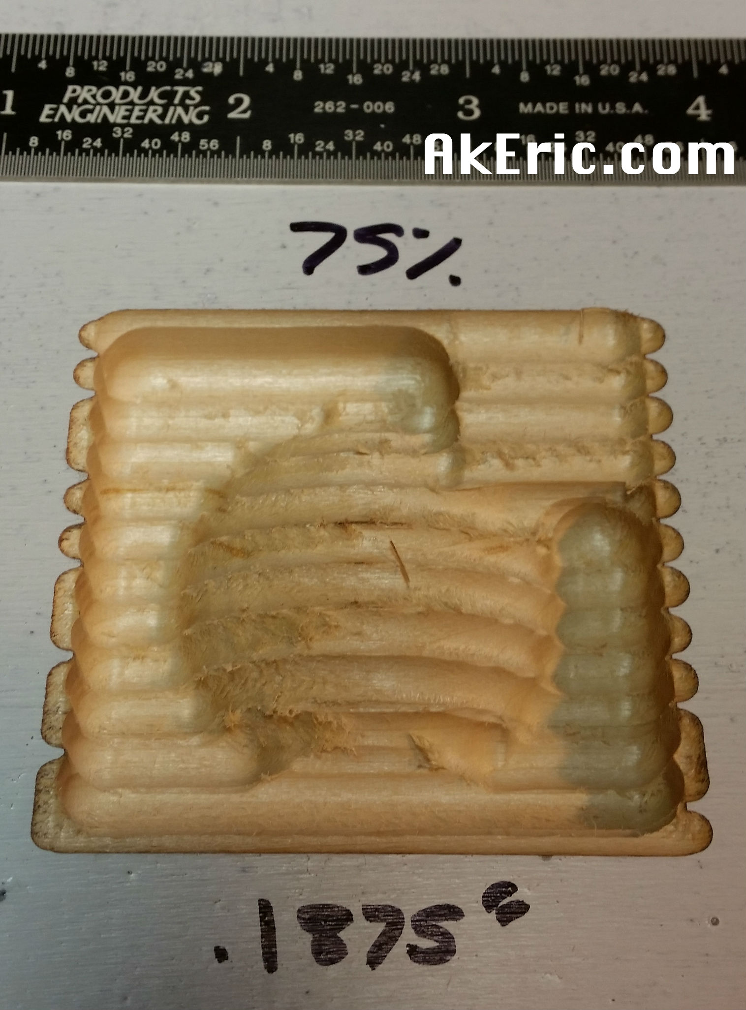
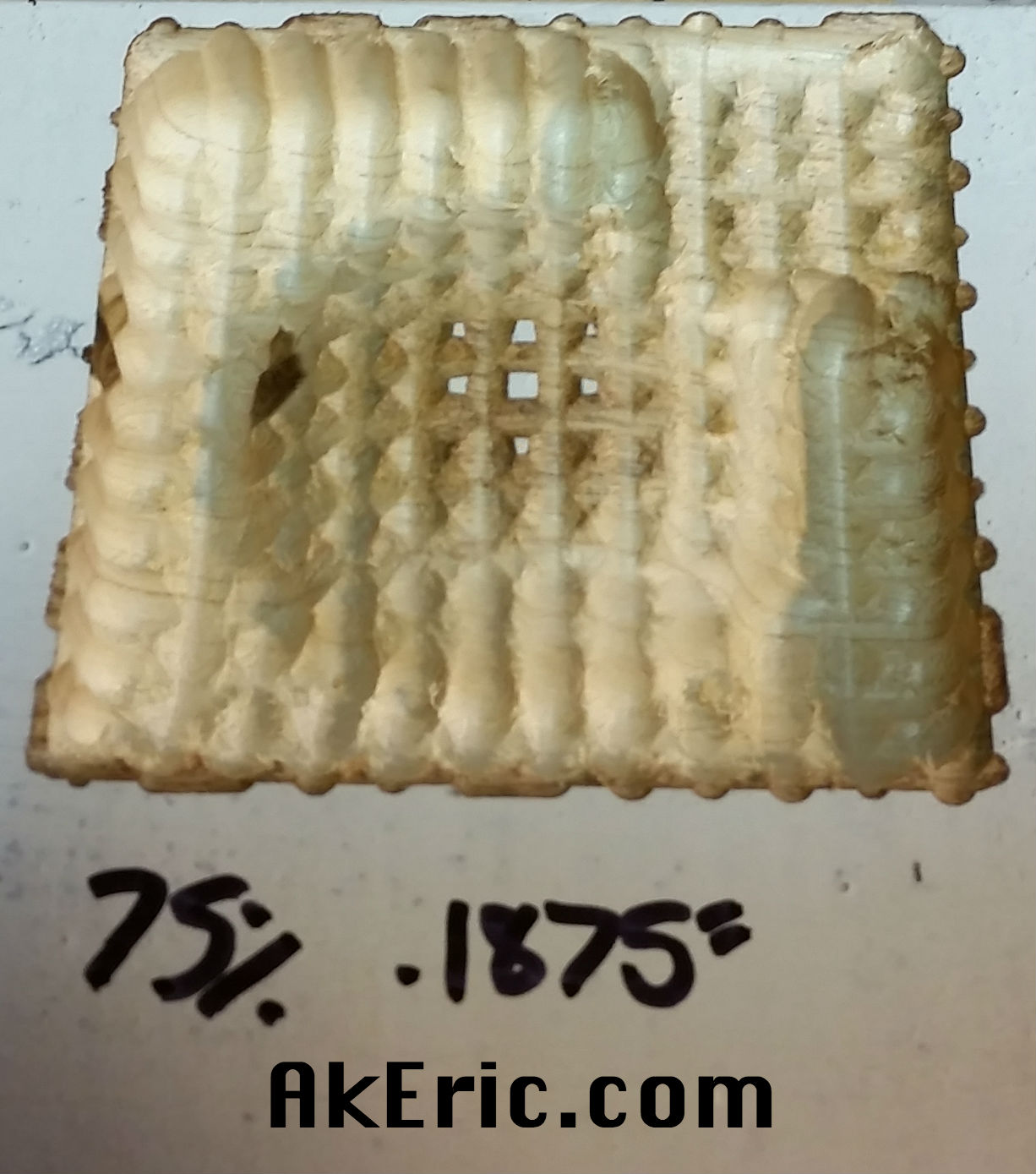
- Note, getting this right is super important! I was having all sorts of print problems (since I’d just chosen a thermistor by name that ‘sort of matched’) until I set it to ‘EXT0_TEMPSENSOR_TYPE 8’ in the firmware, and it’s amazing how much better the print quality got. Of course you may be using a different type of thermistor, but the important thing is get the right value plugged in here.
- ALSO NOTE, ALSO SUPER IMPORTANT: If you later go back to use the online ‘Repetier-Firmware Configuration Tool’ to adjust other settings & re-download, this temp sensor setting will get reset (mine gets reset to 14 every time) : You must manually go back into the configuration.h and set it back to 8 (or whatever value is appropriate for you). I’ve posted this bug to their forum, so we’ll see what the community has to say about it…
- Be sure to set the “Extruder Cooler Pin”, or the fan won’t kick on as the hotend heats up. I set mine to “Fan pin”.
- Be sure to set “Enabled Heated Bed Support” if you have one, and the type of thermistor used.
- Set your extruder’s “Resolution”, or “steps per mm” : Mine is 300 from Marlin (Repetier was 370 by default). I ended up having to set it to 325 based on testing (but via the LCD Configuration menu, and store in the EEPROM, not via the Arduino sketch.)
- Features Tab:
- Be sure to set your “Print cooling fan pin” if you’re using one (to cool the filament as it is deposited). I set mine to “Fan 2 pin”.
- Set “Fan pin for board cooling” if you’er using fans to cool your mainboard. I set mine to “Heater 3 normally used for extruder 2”.
- Set ‘Enable Watchdog’ if you’re doing that (see the next section below).
- At the bottom, set “Homing after Filament Change” to “No Homing”.
- Or in Configuration.h set:
- #define FILAMENTCHANGE_REHOME 0
- If you don’t do this, you may get a bug that happened to me: If you pause the print to reload the filament via the LCD, when the print restarts it’ll go to the wrong location
 This took me a lot of troubleshooting to figure out.
- User Interface Tab:
- Change “Display Controller” to “RADDS LCD Display 4×20”
- I unchecked all the languages other than English
- I set my Machine Name
- Setup ABS & PLA preheat presets.
- Manual Additions:
- Download:
- Note any errors or warnings that appear at the top of that page (in the different-colored callout box. There may be none): I didn’t realize these are actually calculated based on the latest settings, and will change\update every time you go back to the ‘Downloads’ section.
- “Download complete Firmware incl. these settings” the first time.
- Every time after the first, you only need to “Download configuration.h” to update the firmware.
Firmware installation on HD, integrating with Arduino, upload to Due:
- I unzipped the download to my (mac) ~/Documents/Arduino folder, which is the home for all my sketches.
- When I opened Arduino, a “Repetier-Firmware” section appeared in my sketches.
- A txt file is provided at the root of the zip with more specific info to do. One of those things is getting the ‘Hardware Watchdog‘ setup for Due (which is off by default).
- The instructions are all for windows though: I’m on Mac, so none of the copy paths matched up. Finally, I found the directory where I needed to copy everything:
- /Users/<USERNAME>/Library/Arduino15/packages/arduino/hardware/sam/1.6.4/variants -> Copy the /arduino_due_repetier folder from the zip here
- /Users/<USERNAME>/Library/Arduino15/packages/arduino/hardware/sam/1.6.4 -> Copy the boards.txt here. I first renamed the old one to _boards.txt just to not loose anything.
- Upon restarting Arduino, under ‘Tools -> Board’, there is now a ‘Arduino Due for Repetier’ option. Which is what you want to select to enable the watchdog.
- Time to upload to the Arduino. Simple Repetier guide here.
- Don’t forget to fix your ‘EXT0_TEMPSENSOR_TYPE’ to the correct value before upload, if it was changed by the web ui!
- The compile and upload went off without a hitch! LCD came to life immediately after the reboot.
Testing the Watchdog:
To make sure you have the watchdog working, issue a M281 to Repetier Firmware via your host software (I use Simplify3D). If its working, you should see something like this:
SENT: M281
RECEIVED: ok 0
RECEIVED: Info:Triggering watchdog. If activated, the printer will reset.
RECEIVED: TargetExtr0:0
RECEIVED: T:21.34 /0 B:21.25 /0 B@:0 @:0
SENT: M105
SENT: M105
RECEIVED: start
RECEIVED: Info:Watchdog Reset
And the printer should reset in the process. Thanks to Ryan Carlyle for the above tip.
What is the ‘Hardware Watchdog’ doing?
Fine question which I didn’t know the answer to. Gotta love the internet:
Here’s a quote from Dan Newman:
“If the processor is wedged up, then for many/most definitions of wedged up, it won’t be responding to any commands as the software is, well, wedged up. That’s the point behind the hardware watchdog: you enable it with a timeout (e.g., 4 or 8 seconds is common on an AVR). Then your software MUST reset it every N seconds before the timeout expires. If your software doesn’t reset it in time, then the watch dog fires and forces a reset of the processor. Wedged software won’t reset it and so it fires resetting the processor.”
“Watch dog is just a hardware timer. It starts, for example, a 4 second countdown. If you don’t reset the timer before the 4 seconds elapse, then the hardware in the processor causes it to reset (i.e., reboot). So, healthy firmware makes damn sure to reset it more frequently than every 4 seconds. If the firmware locks up or is otherwise having unexpected problems, it cannot reset it and so the countdown completes and the processor is rebooted. To be useful, the electronics and firmware should be well designed: the electronics should be default assert a powered off state for heaters. And the firmware on booting should also turn all heaters off. Likewise for motors.”
And Ryan Carlyle:
“It’s a hardware deadman switch built into the processor. The watchdog has a countdown timer (adjustable but usually a few seconds long) that must be reset by the firmware over and over forever. If the timer ever reaches zero, the watchdog will hard-reset the processor. Specifically for 3d printers, we want to ONLY reset the watchdog timer when the heater powers are managed. That way, if the firmware falls into an infinite loop during a bad SD read or whatever and stops paying attention to the heaters, the watchdog will reset everything. That will then turn the heaters off, unless something else is wrong too.”
Comments on using RAPS128 stepper drivers, and the watchdog, in regards to the “…And the firmware on booting should also turn all heaters off…” comment above:
Ryan Carlyle: “This is something that bugs me about RAPS128 drivers (enable is inverted) and FD-RAMPSv1 (FET is inverted) — the standard reset sequence actually turns stuff on while the firmware loads. Not good behavior. “
Dan Newman: “And when installing/updating firmware they typically enable as well. Yes,
it is annoying. “
People, just use SD6128 drivers…
Connecting the Hardware:
Descriptions below based on this image of the RADDS board.
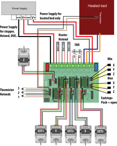
Connecting Steppers:
- I hooked both Z-steppers to the same driver on the board: They conveniently provide two headers there specifically for that. So far, I’ve had no issue raising \ lowering the bed.
- I hooked my “left” stepper to the “X” driver, and the “right” stepper to the “Y” driver. And.. the extruder stepper to the corresponding driver.
Tuning Stepper Drivers
- I’m using 4 SD6128 drivers: One driver for the dual-z steppers, plus one each for X, Y, & Extruder steppers.
- Setting the reference voltage:
- They have a max peak output of 2.2A.
- Based on this doc: http://reprap.org/wiki/RAPS128, it recommends a voltage range between .8-1.6v
- Based on the user guide, the: Current Limit = VREF*2
- To set this, touch one probe from your voltmeter on the pot on the driver, an the other on the RADDS ground. See the picture in section 3.4 of this pdf guide.
- By default they all appeared to be set to around .55v : I dialed them up (clockwise) to just under 1v : Anything higher than that and the steppers would make a terrible sound and I had to reboot the machine to get them to move again.
- Fast-forward: .9->1v is way too much for the steppers: After only 4 minutes of printing they were burning hot to the touch, and were starting to melt their brackets. I dialed their voltage back to .55, and got much cooler-to-the-touch results. As an aside, I’d set my DRV8825’s to .58 volts. After a bit more printing my extruder stepper was doing some skipping, so I pushed it up to .75v, and it’s been doing fine since.
- Lesson learned: Set SD6128’s ref voltage to .75v, this sets the current (from the current limit equation, above) to 1.5A (1.5 = .75*2). Anything higher than that and things start getting pretty hot.
- Update: I swapped out to some RAPS128 much later (as a test only): You should set their ref voltage to 1.1v. Their ‘Current Limit = VREF*0.9125
Endstops:
- I’m still using the “Makerbot style” (or RAMPS style) endstops that I had hooked up to my Rumba.
- Their pin order (starting with the side of the switch) is (sig, -, -, +)
- To hook this up to the RADDS board it’s important to not hook up the +v, just the sig and -: RADDS is a 3.3v system and the LED works off 5v logic.
- My wire colors were Green (sig) Black (-) Red (+). So I just cut the Red (+) line and plugged it in to the MIN XYZ headers on the board (since my machine homes negative X, negative Y, negative Z).
- These switches are NO (Normally-Open) by default: Tripping the switch creates (closes) the connection.
Other Components:
- I plugged my main power, and hotbed input voltage just like the image shows.
- Since I use a relay to actually control the bed power, I wired it into the voltage output for the bed (blue/yellow lines in the image), just like before on the Rumba. In Repetier : ‘Heater 1 normally used for heated bed’.
- Hotend heater cartridge connected to “Heater Hotend 1”. In Repeter : ‘Heater 0 normally used for extruder 0’.
- Hotend cooler fan connected to “Fan 1”. In Repeter: ‘Fan pin’.
- Filament cooler fan connected to “Fan 2”. In Repetier: ‘Fan 2 pin’.
- Mainboard cooler fan(s) connected to “Heater Hotend 3”. In Repetier : ‘Heater 3 normally used for extruder 2’.
- Hotend thermistor connected to “Thermistor Hotend 1”. In Repetier : ‘Temp 0 normally used for extruder 0’.
- Heated bed thermistor connected to… the top plugs (per the diagram), which I’m guessing is actually “Thermistor Hotend 5”? In Repetier: ‘Temp 1 normally used for heated bed.’
3d Printed Cases
I’m sure your Googling is just as good as mine, but I found this nice RADDS & LCD case on Thingiverse:
- RADDS Case
- Note, after print I had to cut a long slot (with my Dremel) through the side that said “Arduino Due” to provide wire access to all the screw-terminals on that side.
- LCD Case
Setting up with Octoprint
I try to use Octoprint most of the time (back using the Rumba/Marlin) for remote print monitoring. I couldn’t get it to recognize the SD card however on the new hardware. Under Octoprint’s Settings -> Feature menu, there’s a bunch of “Repetier specific” options : I checked those all on, and the SD card was immediately recognized.
Also found a slick plugin called the “EEPROM Repetier Editor” that, quote “Makes it possible to change EEprom Values of Repetier Firmware through OctoPrint”. Nice!
In Conclusion
I’ve had it running for a few weeks, now, and have been tuning my print profiles in Simply 3D: All my tests have been running at 90m/sec with no issues, so high hopes for much higher values in the future.
Jump to C-Bot blog index to see all the posts.
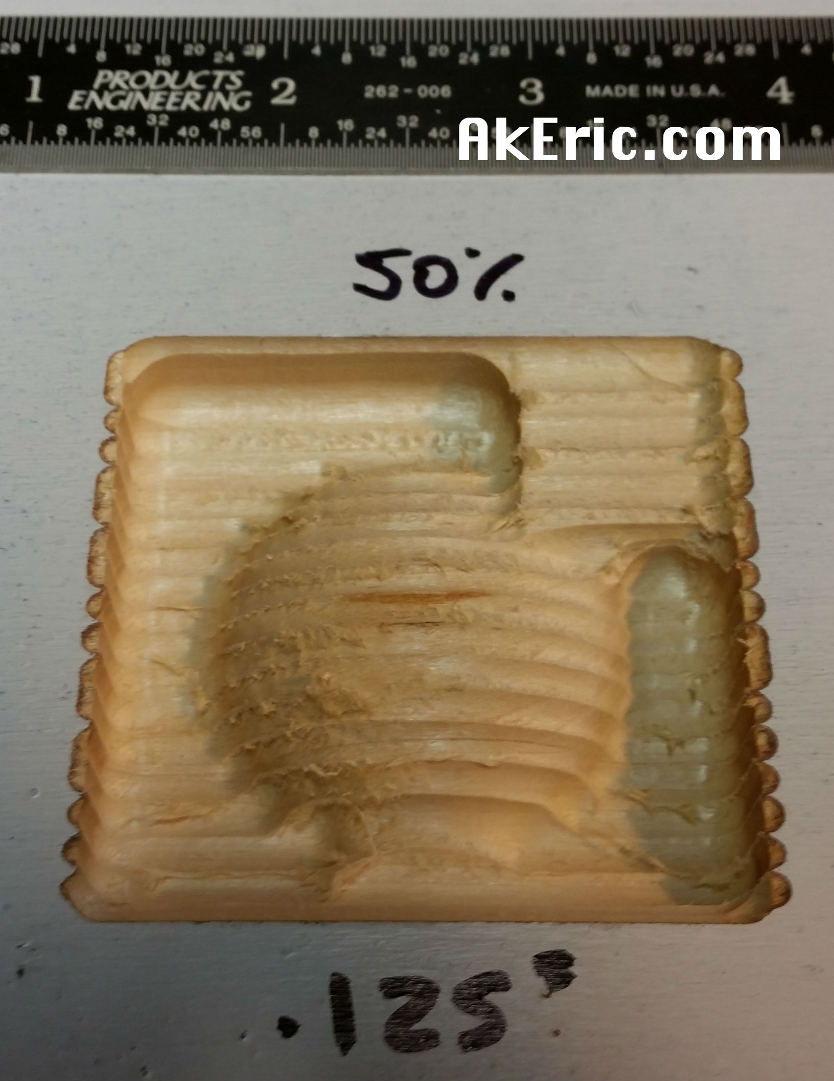
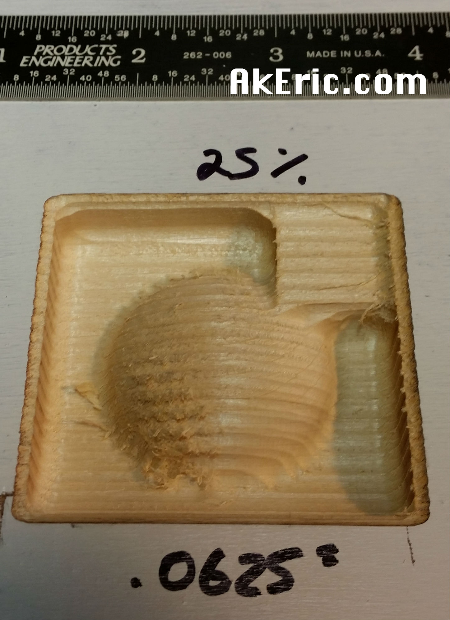
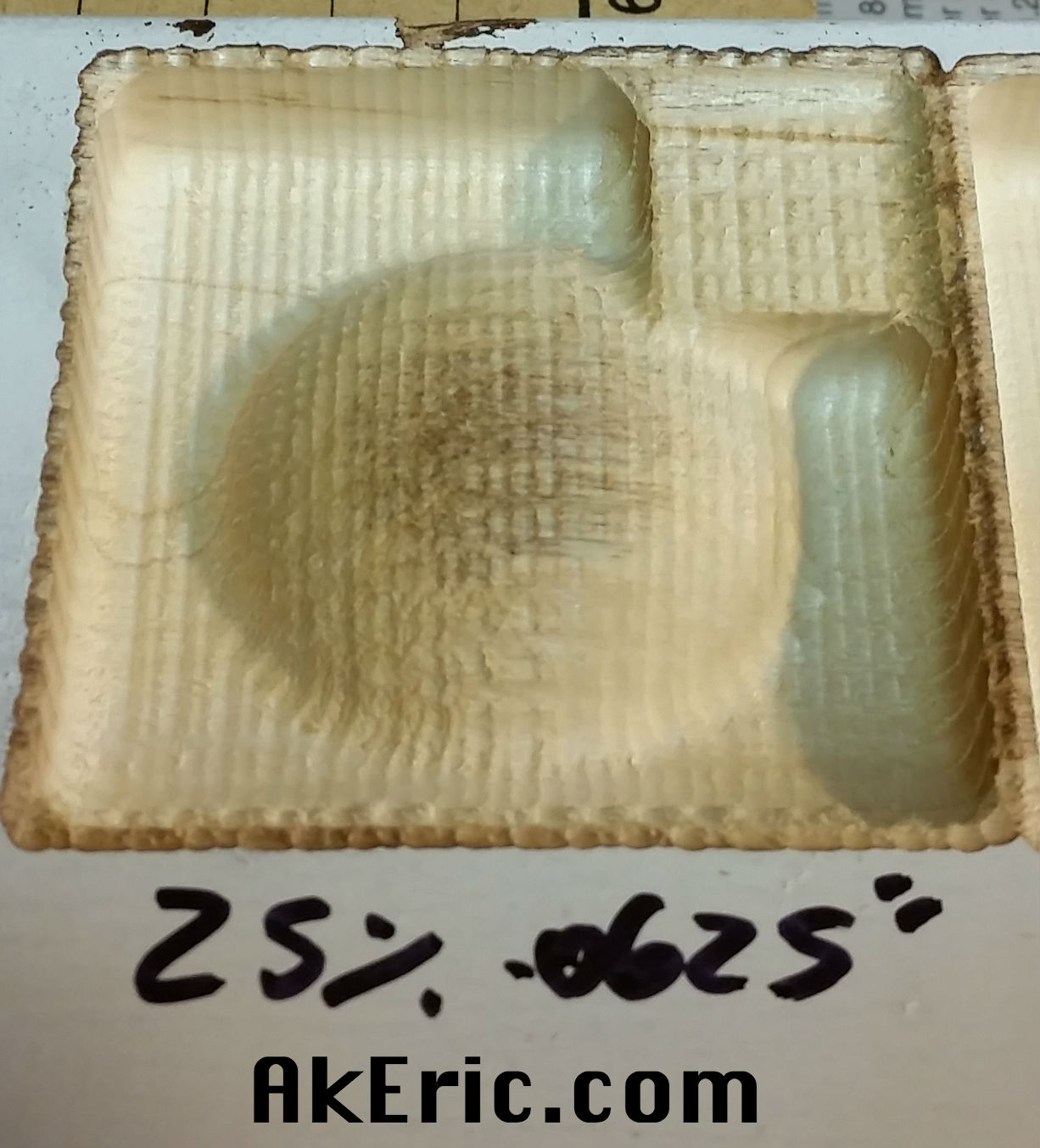
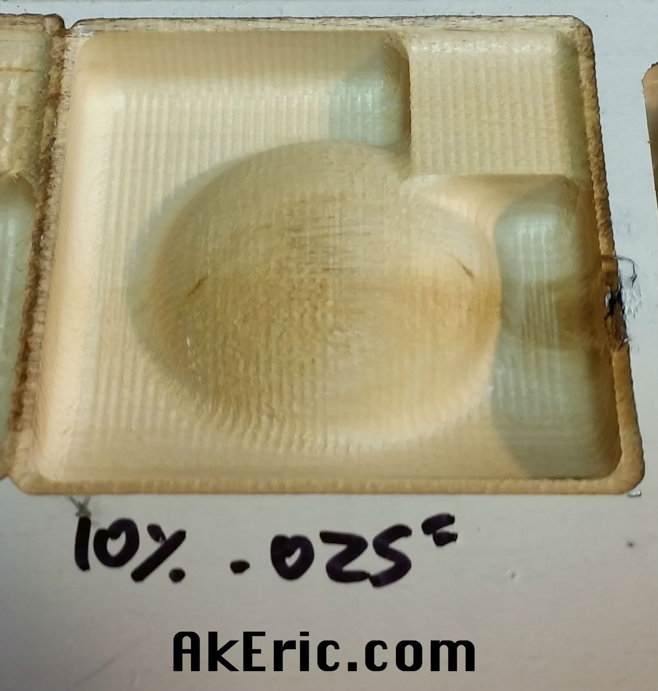
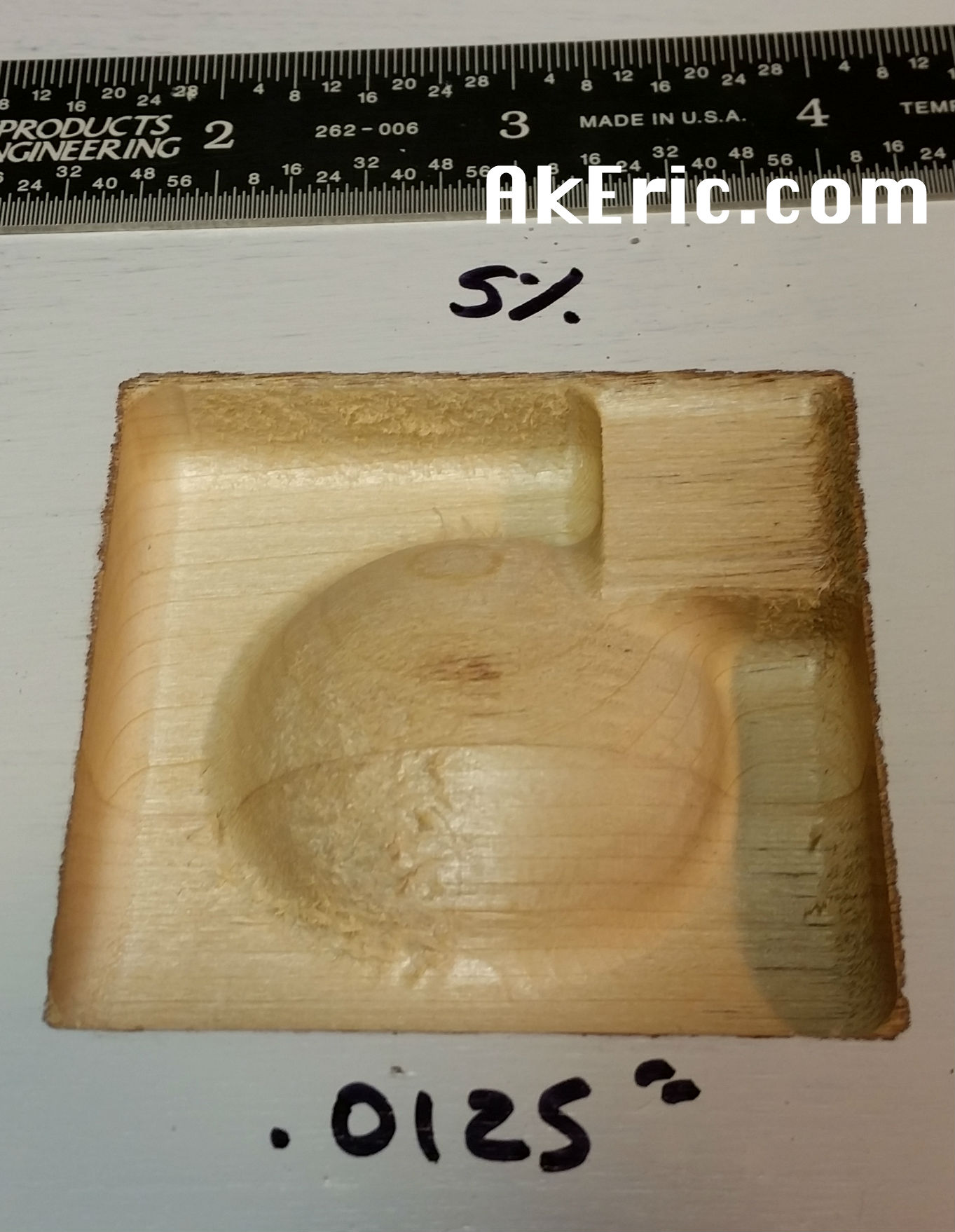
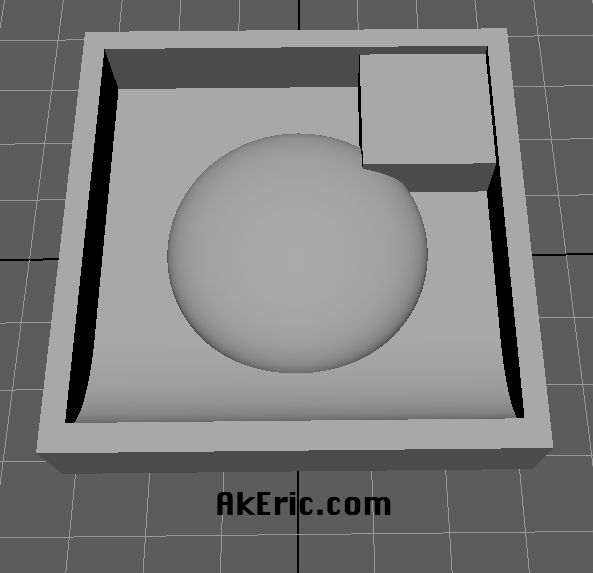 (that’s a flattened sphere in the middle)
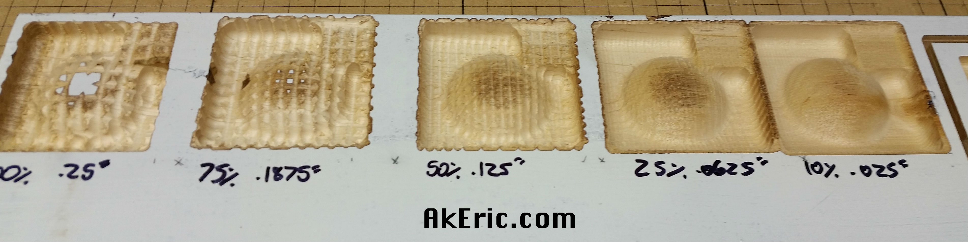 (note, no 5% test here)