Even though the electronics still look like a giant pile of spaghetti out the side of the bot, there wasn’t much left stopping me from actually printing something. But, a few things still needed addressed:
My build-platform wasn’t remotely level, it was drooping way too much on the front. With the help of my wife and son, I loosened up all the bolts holding the cantilevered 20×40 beams to the Z-stage, had my son slightly lift up on the end of it, and I re-tightened everything while my wife helped hold a wrench on the rear of the nuts where needed: That got me able to level it with some z-endstop adjustments.
Based on where the hot-end homes, there’s a 2mm X & 25mm Y offset from the corner of the build platform (calculated my manually moving the toolhead on X&Y via the LCD to the corner of the build platform). I couldn’t figure out where in Marlin to enter these values: Obviously the head needs to move to this position from home and ‘start’ the print there, as 0,0,0. I slice using Simplify 3D, and I finally found these offsets in the “G-Code” section of the Process window, under “Global G-Code Offsets”.
I also needed to configure Simplify 3D to actually recognize this machine: Luckily version 3.0 came out just yesterday, and has a new machine ‘Configuration Assistant’ that made the process of ‘building’ my machine pretty easy.
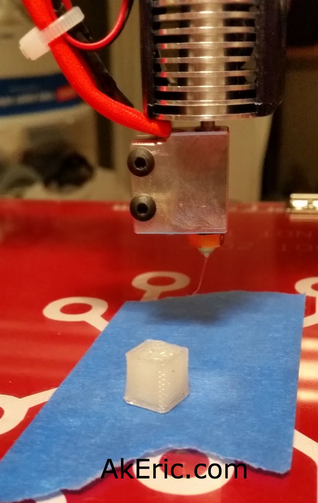
From there, I imported a simple 1cm calibration cube, slapped some blue painters tape on my build platform, and fired it off. It’ immediately started moving, but not extruding: Come to find out, even though I had all my stepper wiring in the Rumba the same, I had to flip the harness on the Bowden extruder 180 to get it to extrude the direction. With that resolved, take two worked flawlessly: A few minutes later, a tiny 1cm cube appeared:
1st print!
This was printed with a 1.0mm E3d-v6 Volcano nozzle, at 500micron layer height. Beefy! Surprisingly using my calipers, it was within .02mm tolerance on all axes: Not bad for a first print!
Safe to say I’m pretty happy that it ‘just worked’ on the first try. Now that I know it works I’m going to clean up all the wiring next, then get into the print calibration phase.
Update: Since authoring this post I have switched my electronics to RADDS, and my firmware to Repetier. See the “Part 31 post” for the latest on it.
Now that my z-stage is moving down and up, and I can ‘auto home’ my printer through the LCD, it was time to get the movement settings and max travel extents calibrated.
Total time: About two.5 hours.
Tuning Movement Settings:
You need to make sure that when the g-code tells your printer to go 100 mm’s, it really goes 100mm. Not 90mm. Not 100.1mm: 100 mm. On bots like my Makerbot Replicator (1) this is already done for you. But when building your own machine from scratch, you need to figure all this out. Otherwise you get ovals where you should get circles, and rectangles where you should get squares.
Pitch : Listed at 2 (distance in mm between each peak), but this value was incorrect for the below calculator. Info below. The value needed in this instance was 8 (the distance in mm traveled with one revolution).
Armed with those numbers, I accessed the “RepRap Calculator” to get me the base values for my bot. I wanted to see if they’d match values Mason had already pre-plugged into Marlin (that mine should very closely match), but I wanted to understand how this system worked: In Marlin’s Configuration.h, I found the line with ‘DEFAULT_AXIS_STEPS_PER_UNIT’ with an array of four values plugged into it {x, y, z, extruder}. Based on the calculator, my ‘belt steps per mm’ came out to 100, which was around what Mason had given me. However, the ‘leadscrew steps per mm’ were 4x (1600) what was listed in the firmware (400). After a bit of research, I realized the calculator wanted to know the distance the lead screw travels in one revolution, not the tooth-to-tooth pitch (2mm). Armed with my calipers, I figured out one revolution traveled 8mm, and plugging that into the calculator gave me a value of 400. Success!
Now for the tuning: I found this great guide (on the Marlin Configuration page) by Neil Underwood that goes through the manual process of telling your bot (in my case, via the LCD) to go 100mm, and then measure with calipers to see how far it really went. Do maths, enter new values into firmware, re-measure, over and over. Not hard, just a bit time consuming:
I just hit one major problems: Very often the Rumba would reject the upload from the Arduino IDE. At a certain point, it took me half an hour to get three uploads. It turned this already slow process into an incredibly slow and frustratingprocess.
I’ve been programming Arduino’s for years and never encountered anything like this (but never on a 2560 like the Rumba uses): Sketch would compile, but when it would go to upload it would timeout, saying this:
avrdude: stk500v2_ReceiveMessage(): timeout
Searching the internets, I found many other people with complaints (not Rumba specific, Arduino Mega specific), but no solutions. Finally, I read one post (which I’ve lost the link to) that had this issue. The fix? Simply swapping USB ports on your PC between uploads. Suddenly I was back in business.
Setting the max travel extents
For each axis, there is an endstop telling the printer to ‘stop moving’ when it hits it. Most printers (like mine) only have one endstop per axis, although you could setup two per axis (min & max) and probably skip this step. If the endstop stops the toolhead\build platform going in one direction, what stops it going in the other? The firmware.
In Marlin’s Configuration.h, there’s a section called “Travel limits after homing”, where you can setup these constraints for X, Y, and Z_MAX_POS. To start, I edited these values to be something much larger than my current volume, since I was going to dial this in manually on my own and didn’t want a small value to stop me before the true extent was reached.
After re-uploading the firmware with the ‘big’ values, via the LCD I manually drove each X, Y & Z axis to what I considered was the ‘safest max position’: Just before a X/Y gantry would hit something on the opposite side with maybe 10mm to spare, or about 50mm above the lead screw flexible couplings so as to not cause any binding. I copied those numbers down from the LCD and plugged it back into the firmware. My final values are:
// Travel limits after homing (units are in mm)
#define X_MIN_POS 0
#define Y_MIN_POS 0
#define Z_MIN_POS 0
#define X_MAX_POS 320
#define Y_MAX_POS 315
#define Z_MAX_POS 530
So my X & Y are clearly over a foot (304.8 mm), so I have no problem filling my whole 12×12″ bed. But the Z is just under 21″, 3+” short of the 24″ build height I was after. This is due to a few reasons: I have maybe an inch before the z-gantry hits the flexible couplings on the leadscrews, and my E3D volcano easily sticks down over 2″ from the X/Y-gantry : If I did a bit of redesign on the extruder mount I could probably move it ‘up’ more and get 2+” back, and I’d be closer to my 24″ height goal. But 21″ isn’t too shabby to start… 😛
Other Notes:
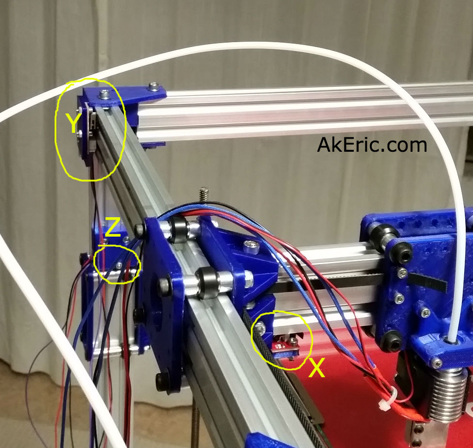
In my previous post I showed how my Y-endstop was at the rear of the bot: This actually blocked the gantry from moving all the way back, and since the extruder is mounted on the front of it, I couldn’t get all the way to the rear of the build platform: I moved it to the front corner instead, and got that clearance back. Now my endstops are all Xneg,Yneg,Zneg, when before they were Xneg,Ypos,Zneg. In the firmware, the settings are thus:
// ENDSTOP SETTINGS:
// Sets direction of endstops when homing; 1=MAX, -1=MIN
// :[-1,1]
#define X_HOME_DIR -1
#define Y_HOME_DIR -1
#define Z_HOME_DIR -1
Update: Since authoring this post I have switched my electronics to RADDS, and my firmware to Repetier. See the “Part 31 post” for the latest on it.
After posting my z-stage problems to the C-bot forum, they suggested I try a couple things: Loosen up the bolts on the ACME lead-screw blocks, and switch to using dual motor drivers, rather than one, like I’m currently doing.
I loosened things up, and it helped a negligible amount, but I was still unable to predictably raise the build platform. So, I decided to dig into Marlin and enable dual-z-steppers.
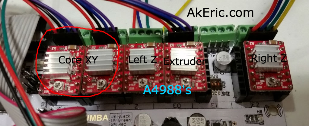
Which I did, and then added an additional A4988 driver to the Rumba board to make use of it:
A4988 Drivers, with dual-z support.
I added the additional A4988 to the “Extruder 2” plug (on the far right), plugged the right z-stepper into it, and gave it a go: The steppers would only lower, not raise. NOW what?
Looking at the Marlin code, I noticed that the block I enabled (starting with ‘#define Z_DUAL_STEPPER_DRIVERS’) to support this looked different from the same block in the “Marlin Configurator“: It appeared that it was also enabling “dual z endstops”, which I didn’t want to happen. Rearranging the code resolved this, and now I have a bed that both lowers, AND raises. Finally. I was going to post this code-fix, but I diff’d the Configuration_adv.h file Mason had given me with the one I pulled down from GitHub, and that code section was radically different. I’m not sure which is newer\older. At least mine works now…
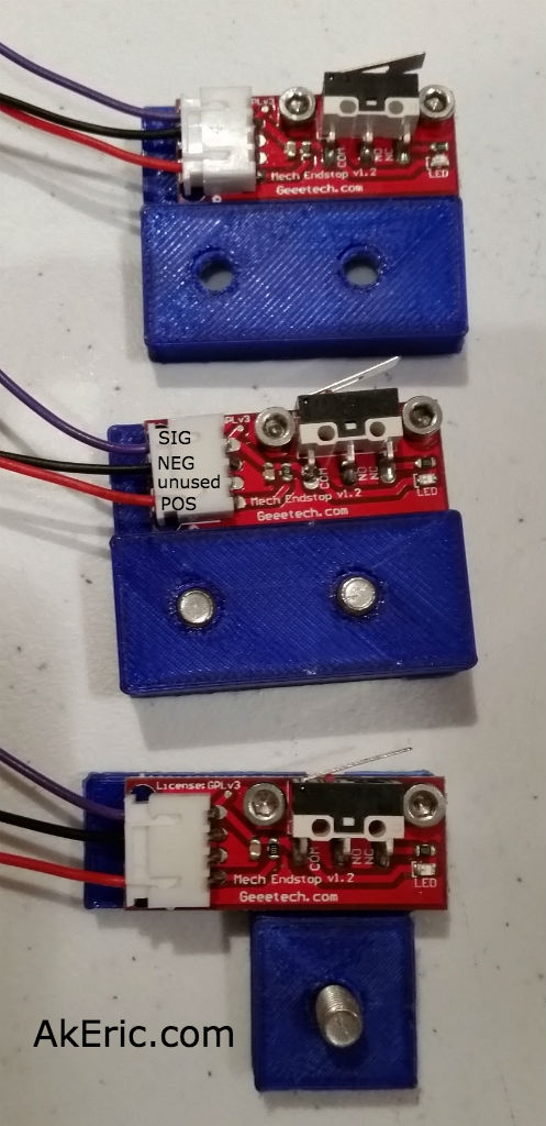
Now that I have the z-stage working, I decided to focus on the endstops: I had mocked them up earlier, but didn’t have them wired properly… at ALL. I spaced out and thought I only needed two wires (+-), but in reality you should also hook up signal, so the LEDs light up. More splicing and crimping ensued, and I got the Geeetech v1.2 endstops wired up correctly, based on this great pic Mason pointed me to…
… living in this thread, that explains it pretty plainly. Thus the end results:
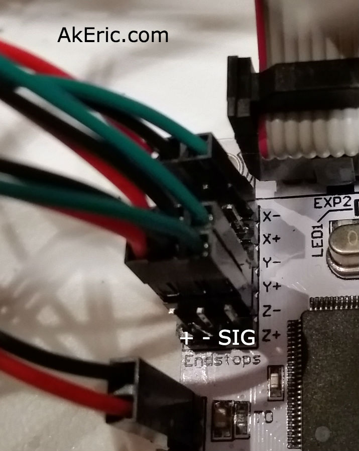
From there, it’s getting them plugged into the Rumba correctly:
Note: Since I took this pic, I’ve changed my Y endstop so it is now Y-
Here’s the logic behind it:
Looking down on the build platform, zero XYZ is in the bottom left corner. +X is to the right, +Y is towards the back, and +Z is up.
The X-endstop is on the left side of the Y-gantry, that the extruder blocks hits when traveling left: It is in the “negative” position, thus X-.
The Y-endstop is mounted on the top-left-rear corner of the printer, and the Y-gantry hits it when it moves back in a ‘positive’ direction. So it’s Y+.
Note: Since I authored this page I’ve moved my Y endstop to the top-left-front corner, so it’s really Y- now.
The Z-endstop is mounted towards the top of the left rear leg of the printer, that the Z-stage hits when it lifts up. Since when the build platform drops it’s going in a ‘positive’ direction (or, instead, imagine the build platform on the bottom of the printer, and the nozzle lifting up instead, which is effectively the same thing), it means it starts at the negative position, thus -Z.
Note: Since I took this pic, I’ve changed my Y endstop so it is now Y-, or on the front-left of the bot, rather than rear-left as in this pic.
Once the endstops were wired up, I was able to ‘auto home’ the whole system from the LCD, and… it worked.
Finally, no more blockers… next up will be calibrating the XYZ travel distances.
Update: Since authoring this post I have switched my electronics to RADDS, and my firmware to Repetier. See the “Part 31 post” for the latest on it.
Instaling Marlin
Once all the wiring was mocked up, was time to get Marlin installed: The Rumba already had a cut of Marlin on it, but I need an updated version turning on the coreXY mechanics.
So I went to the RepRapDiscount Smart Controller page to glean what it had to say: I wants you to set your board type to ’30’, which ain’t a Rumba, and other things that didn’t seem to apply to my board.
Mason sent me his cut of Marlin, and after I got it installed my LCD came back. I need to diff files and see what I did wrong and he did right. He did remember that he ‘had to go modify the LCD code to get it to work’. Scary!
Tuning the stepper drivers
(Note, I have since replaced these with DRV8825’s, check out this post to see a better way to tune them up).
Once the LCD was working, I could start manually tuning the A4988 motor stepper drivers. My previous post talks about the math to calculate the values, but that sort of goes out the window when you turn things on. From the “Motor Calibration” section of the RepRap Wiki, they say:
“Each Pololu has a trimpot located next to the heatsink. The trimpot controls the current that is sent to each motor. Turning the trimpot counter-clockwise reduces the current to the motor, turning it clockwise increases the current to the motor.
Start by adjusting the trimpot down until your motor vibrates on the spot rather than turning cleanly. Now turn the trimpot in a clockwise direction in small increments (1 eighth of a turn) until the motors just start running. Then give the trim port a final turn of about 1 eighth of a turn and your should be good to go.”
So I did a bunch of that and got the X/Y steppers working, + the extruder. But I couldn’t get my dual-Z steppers to work. I had both stepper wires running into the same green terminal blocks. Mason suggested maybe I connect one to the terminal blocks, and the other to the pins behind it: That made things seemingly work better, but the z-stage still wouldn’t move. I loosened the couplings that hold the leadscrews to the steppers, and then they’d start to turn. But if I tighten them back up, no movement. Currently stuck here. Grrr…
Note: I’ve updated this post to reflect the most recent 3.0 release, in June 2015
I started 3d printing in March of 2012 on my Makerbot Replicator (1). I used ReplicatorG as my slicer, since that was the primary option at the time. When Makerware (now Makerbot Desktop) was released I switched to it, and never looked back. I’ve found success with it, and really only have a few complaints. Namely that it slices very slowly (can take hours in some cases), and while you can make custom profiles (which I use), it’s clunky editing a text file (I shouldn’t really complain about that, considering how much programming work I do). I eventually got Sailfish firmware loaded on my Replicator 1 as well.
Christmas 2014 I decided to gift myself with Simplify3D (S3D below): I’d read a lot of good about it online, and decided to give it a shot. $140 isn’t cheap for a dedicated slicer with no trial version, but bit the bullet anyway (well, after testing it for a few weeks at work first).
In July of 2015 I finished building a new Core-XY bot running Marlin, and now use S3D for its slicing as well.
This blog post will be a continuing repository of my thoughts as I continue to learn and work with it: S3D does a lot of good, and up until the release of 3.0 there were several areas that rubbed me the wrong way. Note I started working with version 2.2.0, which sounded like a pretty major update, and have been pleased with many bug fixes in 3.0. Also know that the bulk of the “Cons” (many of which have been fixed in 3.0) discussed below have already presented directly to the S3D developers.
This will be organized into three main sections:
Pros : Things I really like about it.
Cons/Bugs : Things that could be done better.
Workarounds : Cons that I’ve found solutions for.
Fixes : These are past cons/bugs that later updates have addressed.
There are more things than this I consider “pros”, these are just some of the stand out ones I’ve encountered.
Really Fast Slicer : I’ve played with Cura and I’ know how fast it is. I’ve not compared S3D’s speeds to it. But compared to Makerware, it’s exponentially faster. Minutes in Makerware are seconds in S3D.
Good quality output : At minimum, prints just as good as the best stuff I got out of Makerware.
Great GCode Previewer : Being able to preview every layer of the slice, and to visualize the speed in which it will be printed is invaluable. That coupled with the slicing speed turns this into an actual iterative process: Change a few settings, preview. Change a few settings, preview. Etc.
Cross Section View : Allows you to visualize any cross section of your model, or GCode. So handy!
Many Knobs To Twist : Each “Process” is organized into multiple tabs giving you complete control over just about every setting imaginable.
Tooltips : A little thing, but every setting in a Process has a tool tip telling you about it. Which is really important, considering there’s no official documentation.
Adjust Settings Per Layer : Great option: You can set each “Process” to a layer range, completely adjusting all the settings as needed.
Different Settings Per Model : Not only can you split settings based on layer, each individual model can get its own Process with individual settings.
User Support : Getting feedback/support/help from the developers seems prompt.
Supports many printers: You can take your knowledge with you as you change hardware: When I built my new machine, even though it has completely different firmware than my previous printers, I was able to roll all my exiting S3D knowledge right into it.
Tethered Printing : If printing tethered, can adjusting settings (speed, extrusion, temp) on the fly while printing, issue live GCode commands + get a live play-by-play in the GCode previewer.
Great Support Material Creation : Create it automatically or by hand, either way it prints well and removes easily.
Successfully prints intersecting models : This is a big one: I’ve had issue in the past (Makerware) where two models were brought into the build platform and made to intersect (on purpose) : Makerware didn’t always like this. As a test I brought in 1500 separate obj files, all intersection in different ways, and it sliced perfectly, combining mesh were appropriate so there was no intersecting extrusions.
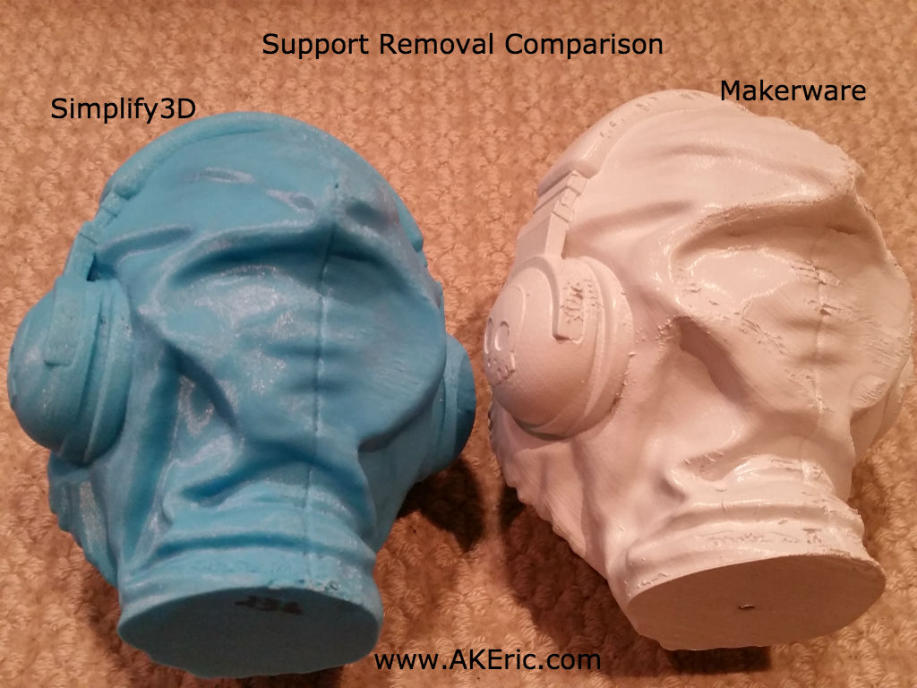
Fantastic Support Generation:
Not only does it create create great auto-generated support (except a bug mentioned below), it allows you to place your own. In addition, it allows the support to become more complex as it approaches the surface, to speed support printing and provided better support overall. Plus, it tears free amazingly well: In the below pic, S3d is on the left, Makerware is on the right (painted white), they both took around 25 hours to print (they’re the size of big grapefruits): The makerware supports required pliers to remove, and there is still much cleanup needed. The sS3d support easily removed just using my fingers, and left minimal scarring on the print.
(click to zoom)
Great infill options (new in 3.0) : A variety of different infill for both strength and speed.
Cons/Bugs
No (official) Online Documentation : While there are tooltips for all the settings, there should be a more detailed overview of all the setting online. Their support is really responsive, but I can’t see a downside to providing real documentation.
The “Center And Arrange” option only moves things, won’t rotate them : The tool could use a better packing algorithm that not only moves stuff around, but can intelligently rotate them as well.
The Estimated Print Time can be wildly off :
Makerware is pretty consistent when estimating time: It always over-estimates by about 20% in my experience. S3D however is all over the place: I’ve had a print estimated at 3.5 hours take close to 7. Most of the time though, it appears to underestimate the print times, but it can vary from 50%-10%. Can’t make much rhyme or reason out of it, other than it’s a pretty useless number
After working with the software, it looks like print times on Makerbot machines (Sailfish firmware) are way off, but on machines with Marlin firmware, it’s pretty accurate. I’m wondering if it has to do with the Makerbot x3g conversion?
No Trial Version : Since this is paid software, make a trial version so more people can try before they buy. Maybe it disables save, but even giving access to the GCode previewer & process settings could sway more people its direction.
Auto-generated support can completely miss ‘floating features’ : Picture a stalactite hanging from a cave ceiling: S3D won’t auto-place support under it’s tip: It’ll let it hang free in space, completely unsupported, failing the print. It’s up to you to check over you model completely, making sure support has been placed correctly. I have a thread on the forum here illustrating this. I really hoped this would be fixed in 3.0, but it has not
It does no toolpath simplification for highres mesh: This means high-res small stuff will print poorly, since you get super-small toolpaths that make your machine do a dance. S3D argues you should give it good mesh. I argue that I shouldn’t have to auto-decimate every mesh I throw at it (since auto-decimation can screw up fine features)… makes printing scaled stuff far more of a hassle that it should be. I show this issue visibly via this post, under the “High Res – Low Quality” section.
Thin wall printing isn’t supported. Say you have a 1.0mm volcano nozzle, and the wall you’re trying to print is .5mm thick : The slicer will just disregard it. This is a hot topic in the forums. If a slicer like Makerware supports it (they call them spurs, or single-thickness walls) S3D should. Otherwise you have to generate new models for new nozzles, what a nighmare.
Black box: They tend to release a new version once a year, but you don’t know when, nor what features will be in it. I’ve asked them if there was any sort of known list of improvements, and none was provided.
Workarounds
Holes In The Roof :
I had a continual problem when printing at 100 micron where there would be holes towards the top of the roofs in my prints. Driving me crazy.
I finally tracked down the problem: I would create my 100 micron profile by duplicating a 200 micron profile. In the 200 micron file, I’d have 3 roof layers set: That’s a roof .6mm thick. But I wouldn’t adjust it in the new profile (since I’m used Makerware, which allows you to define a fixed roof thickness, rather than number of roof layers). So when it would print its roof, it would print 3 layers at .1mm: A total of .3mm thick. The equivalent of one and a half .2mm layers. Not nearly enough for coverage.
The lesson learned is: When you change your layer height, you also need to change your roof layers (and floor) to match. I’d print 6-8 roof layers at 100 micron to get adequate coverage.
Fixes:
Weak Infill : Addressed in v3.0
Only One Type Of Infill : Addressed in 3.0
Not Ready For Dual Extrusion Yet : While I haven’t tested this yet, it looks like 3.0 addresses many dual-extrusion issues.
No Undo : Addressed in 3.0
When translating mesh, it always snaps to a top view : Addressed in 3.0
Unable to fully translate\rotate\scale on all axes interactively with the mouse : Addressed in 3.0
No Option to “Scale to Max Print Size” : Addressed in 3.0
When in GCode preview mode, you can still accidentally move mesh : Addressed in 3.0
No Orthographic Cameras : Fixed in 3.0. But it’s sort of hidden in the preferences window, so it’s easy to toggle.
“Model Settings Window” related : All fixed in 3.0
When changing values via the spinners, it’s a fixed (large) step amount. These should be user configurable for precise control.
Can’t change “Object Size Dimensions” : You can change the scale of an object, but you can’t set it’s absolute size. C’mon, Makerware does it…
Changing the Trans\Rot\Scale values don’t effect anything in the “Calculated Properties” section until you reopen the window: It should be a bi-directional connection allowing either to be edited.
It’s a modal dialog, meaning you can’t do any interaction with the rest of the software while working with it. Like say, change the camera view, since this dialog is blocking the view of your model…
I takes up a lot of screen real-estate: On my laptop it obscures a quarter of the screen, making it a dance to move it to some location where it won’t obscure the model I’m trying to transform (see the above issue).
The transform values aren’t saved between sessions. Meaning, if you translate, rotate and scale an object to specific values, after you save, close, and reopen the scene, the model will be in your transformed position, but those settings will be set back to zero: Makes it hard to later make precise adjustments based on the original size of the model
Strange behavior when changing the default hotkeys : I’ve not tested this, since the new hotkeys are pretty good, but I’m guessing this is fixed in 3.0
Conclusions
Is S3D worth the money?
This is really a personal questions, based on your needs. For myself, especially since the release of 3.0, I’d give it an easy yes.
If you were going to make a business out of 3d printing, I’d give it a resounding yes: While I’m no expert in all the slicers out there, I’m not aware of any other slicer that provides you with the features S3D has.
With v2.2, it felt close to greatness, but fell a bit short. With the release of 3.0 though, addressing so many issues, it really feels like a full-featured piece of software now.