Posts Tagged ‘ inventables

Building the C-Bot 3d Printer : Part 33 : Machining a mic6 aluminum removable build plate

Jump to C-Bot blog index to see all the posts.


Overview

I’ve been using removable glass build plates for years on both my Makerbot Replicator 1, and my custom C-Bot:  I get double-thick glass cut at my local hardware store (Orchard Supply Hardware has had a great price on this), always thinking it was ‘totally flat’.  But is it really?  My C-Bot has a 12×12″ heated build platform.  When I go to level it with the glass, I get each of the four corners dialed in perfectly.  But the middle always sags slightly… even though it’s glass.  Double-thick glass.  But glass is actually somewhat plastic, and this sag has always bugged me.

Back in December I assembled my 1000mm X-Carve CNC, and it’s been so much fun cutting wood.  I knew it could do aluminum as well, but needed  a project.  And that’s what this post is all about:  Using my X-Carve to machine a new removable build plate out of .25″ mic6 aluminum for my 3d printer.  I am so happy with the results.

Sourcing the material

Before I started this, I had no idea what ‘mic6’ aluminum was.  It’s also referred to as ‘cast aluminum tooling plate’ or ‘ATP’, since mic6 appears to be a trademarked brand name.  Simplistically, it’s a standard for (among other things) a very flat aluminum plate, to .001″.  After reading a plethora of forms, and researching my local options, I settled on Midwest Steel And Aluminum’s “Cast Aluminum Tool & Jig Plate“, .25″ thick, 12×12”, which came to about $20, and the ground shipping another $20.  I could have bought it locally for $45 + tax (ugh).

A note on the order:  The plate was packaged in one layer of cardboard, that was it.  It appeared to have been dropped several times in-transit, 3 of the 4 corners were blunted, and there was an small indentation in the middle of plate itself.  If I was using this for something really precision I would have returned it.  Just a note to tell them to ship it better if you go this route.

Once it showed up, time to make some cuts!

Initial cuts

When I first got the plate I knew I had to notch a section out of each corner, since the heads of the bolts that hold the MakerFarm heated build platform stick up about 1/8″ish from it:  I didn’t want the plate resting on the bolt-heads, so I need to make little pockets for each.  Before I even considered my X-Carve CNC, I figured I could use my drill-press to pocket these.  Long story short:  It did not work well, and made a mess of the corners.  Based on that frustration I went down the ‘how about I use that dormant CNC right next to the drill press…” road.

For all below cuts, I used the same 1/8″ 2-flue upcut carbide endmill.

Since these cuts were so simple, I used Inventable’s Easel: I designed a circle with a diameter of .4″ across, .175″ deep, and used that to pocket each of the four corners already mangled by my drill press.  I used the default ‘aluminum’ Easel setting (5 ipm, .003″ doc, DeWalt on speed 1) with the first pocket (which took about 20 minutes), then started cranking it up: By the final pocket I had it running at 20 ipm at .01″ doc, with the DeWalt on speed 2, taking about 5 minutes..  It did great, and the bit was cool to the touch after the cuts.  When all four pockets were complete, it fit right on the bed with no collision with the bolt-heads:

cornerPocketAll the rough stuff to the right of the bolt-head was the abuse by the drill-press.

I have four bulldog clips that hold the plate on, one on the middle of each side.  The issue is even though I’ve bent them down to move them out of the way, parts of them still stick up slightly, and on a large print the nozzle could collide with them.  So going back to Easel, I designed a new rectangular pocket that would keep the bulldogs out of the way of the toolhead.  These were 2.25″ x .3″, cut .075″ deep.  I positioned them in the center of the left\right sides of the build plate, but had to offset them on the front\back based on my leadscrew config.
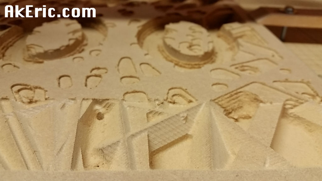
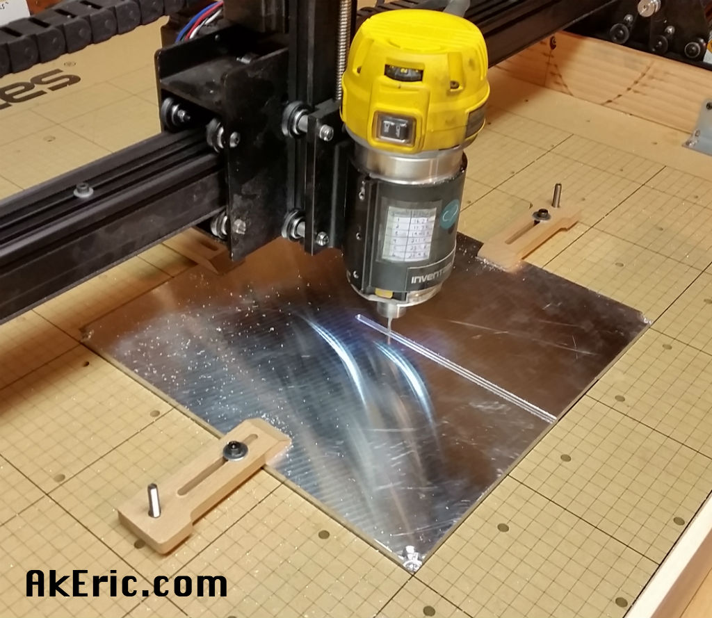
An in-process cut:

bottomPocketCut

And all four final cuts:

bottomPockets

Installed on the printer:  No more clearance problems with the bulldogs! :)

topBulldog

Prepping the plate

I use a highly secret (50% wood-glue, 50% water) slurry on my build plate to get PLA to stick.  But the mic6 is so smooth, I first scoured it with steel wool for several minutes to give the glue something to bite into.

Note for the future:  First, use something like lacquer thinner\acetone\mineral spirits to clean the plate of any oils:  Quite to my surprise, after many minutes of scrubbing, I could clearly see my handprint on it.  The oils deposited from my hand actually protected it from the steel wool.  So I went back and liberally scrubbed it with lacquer-thinner soaked rag, then went back to the steel-wool treatment again:  No more handprint.  Be sure to wipe it down with lacquer thinner after the steel wool too:  The wool actually leaves quite a bit of itself deposited into the aluminum.

After the plate was scrubbed, cleaned, and glue-slurry applied, I did some test prints.  And while the flatness was super awesome, I realized something very quickly:  The slicer said the bed heated up waaaay faster than it actually did:  For big prints in PLA, I’ll heat the bed up to 60c.

It dawned on me that the thermistor that does the temp reading is taped to the bottom of the MakerFarm heated build platform, while the thing being printed is sitting above it on .25″ of aluminum… that is taking much longer to heat up.

After brainstorming, I came up with the idea of cutting a groove into the bottom of the plate, that I could tape the thermistor into:  It should then be reading the temp from the removable plate itself, providing a much more accurate temperature.  This means I’ll also need to snip the leads running to the thermistor and install a barrel-jack into the mix to allow for the plate to be removed, since there’s now a sensor taped to it.

Secondary cut

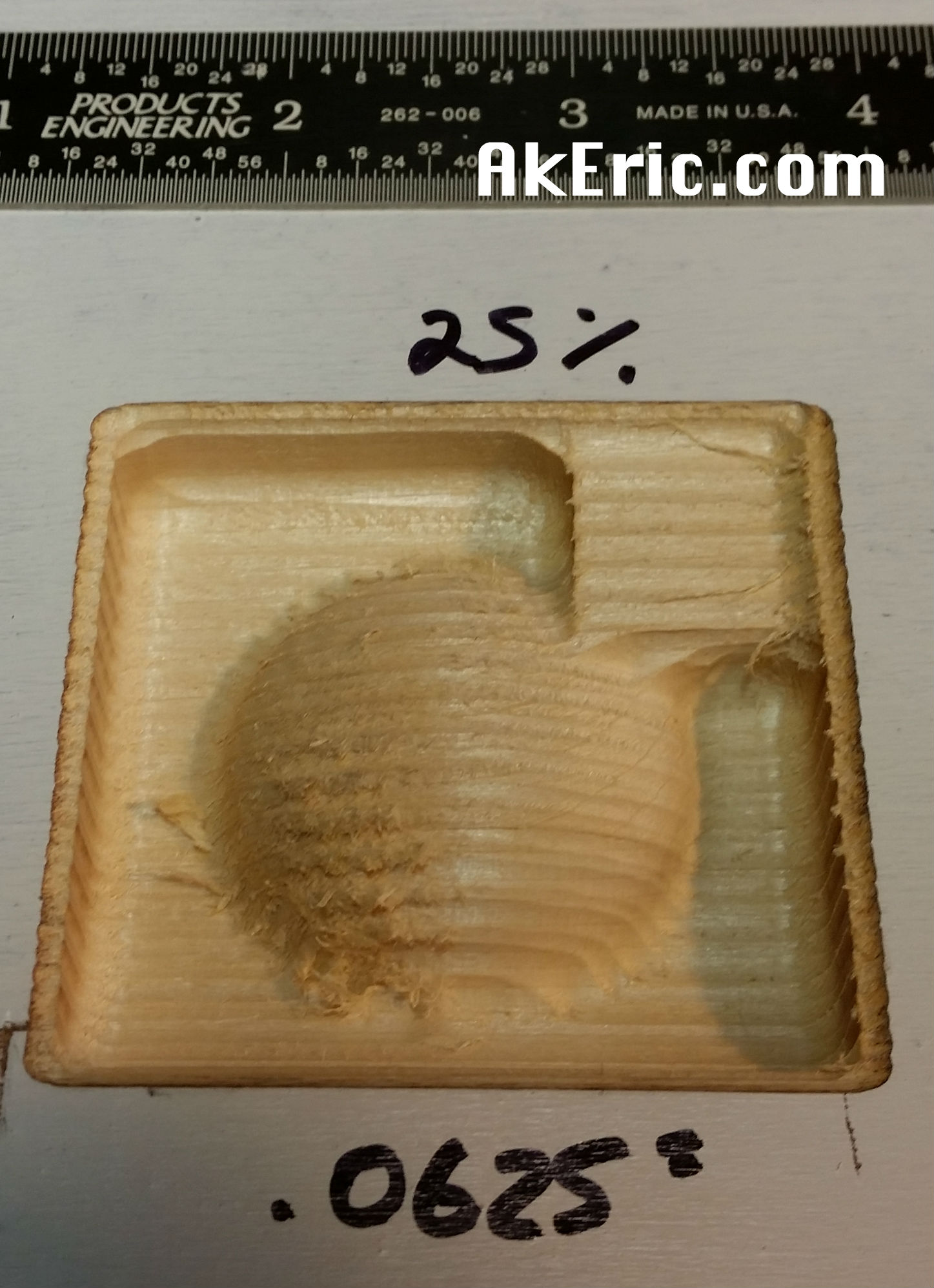
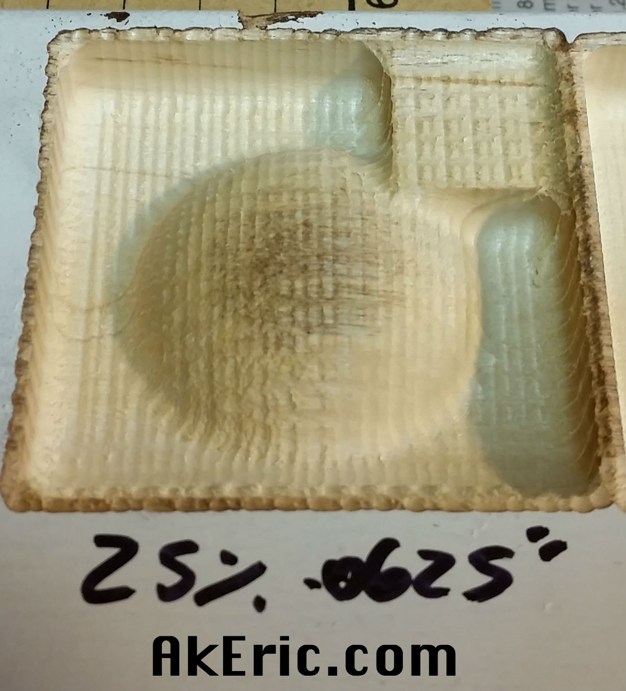
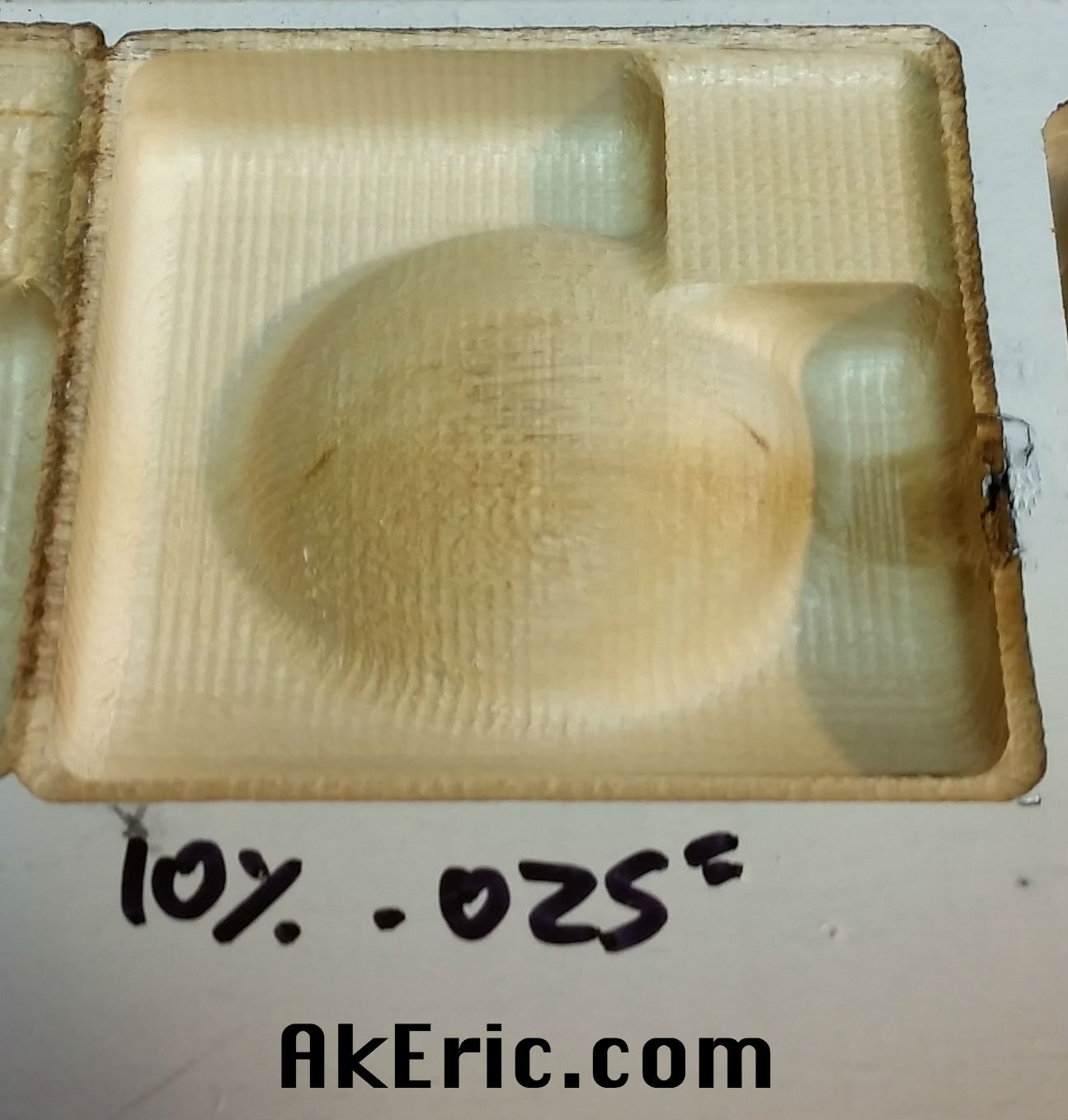
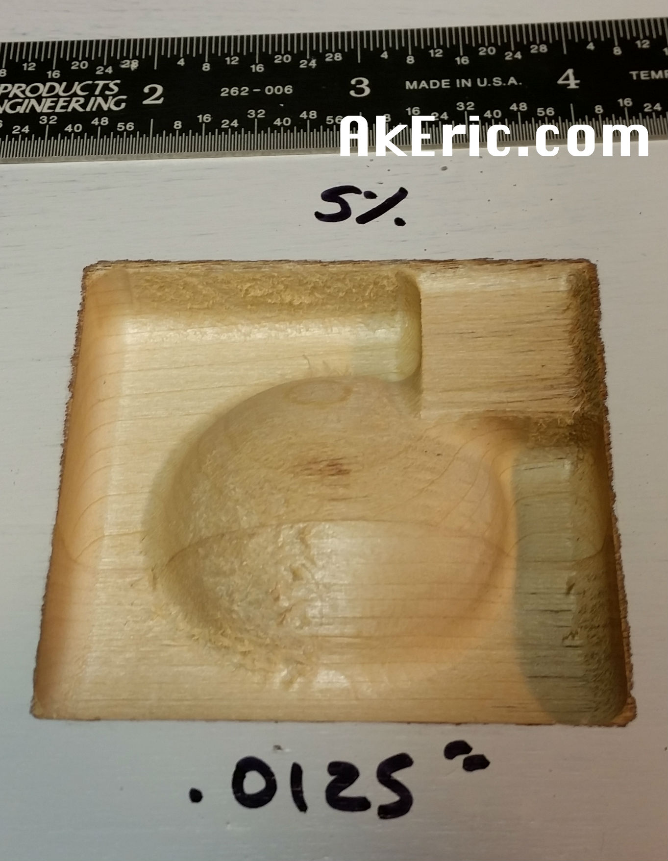
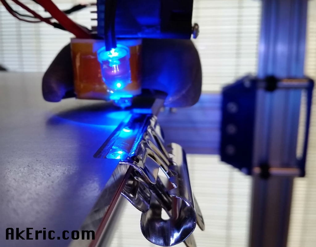
Going back to Easel, I designed a .5″ wide groove cut .0312″ deep that I could recess the tape into, then another smaller groove .2″ across and .1″ deep to run the wires to the thermistor.
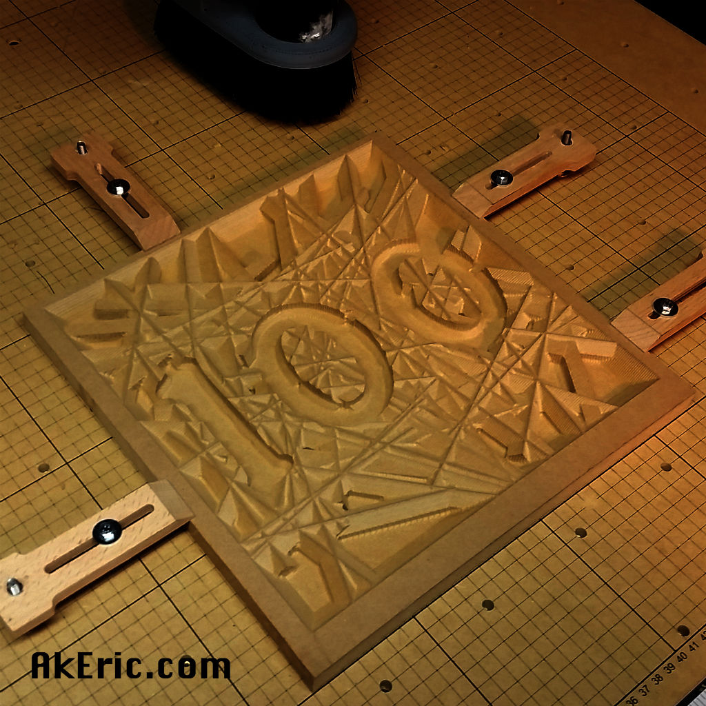
Here it is mid-cut:

bottomGrooveCut

Cut gotchas:

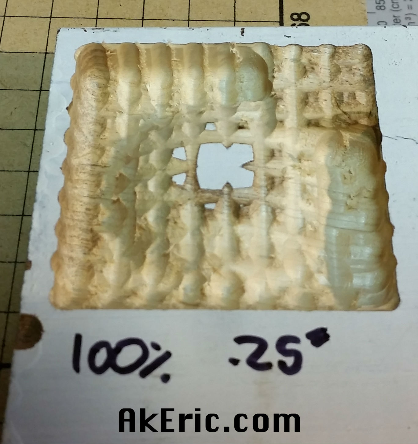
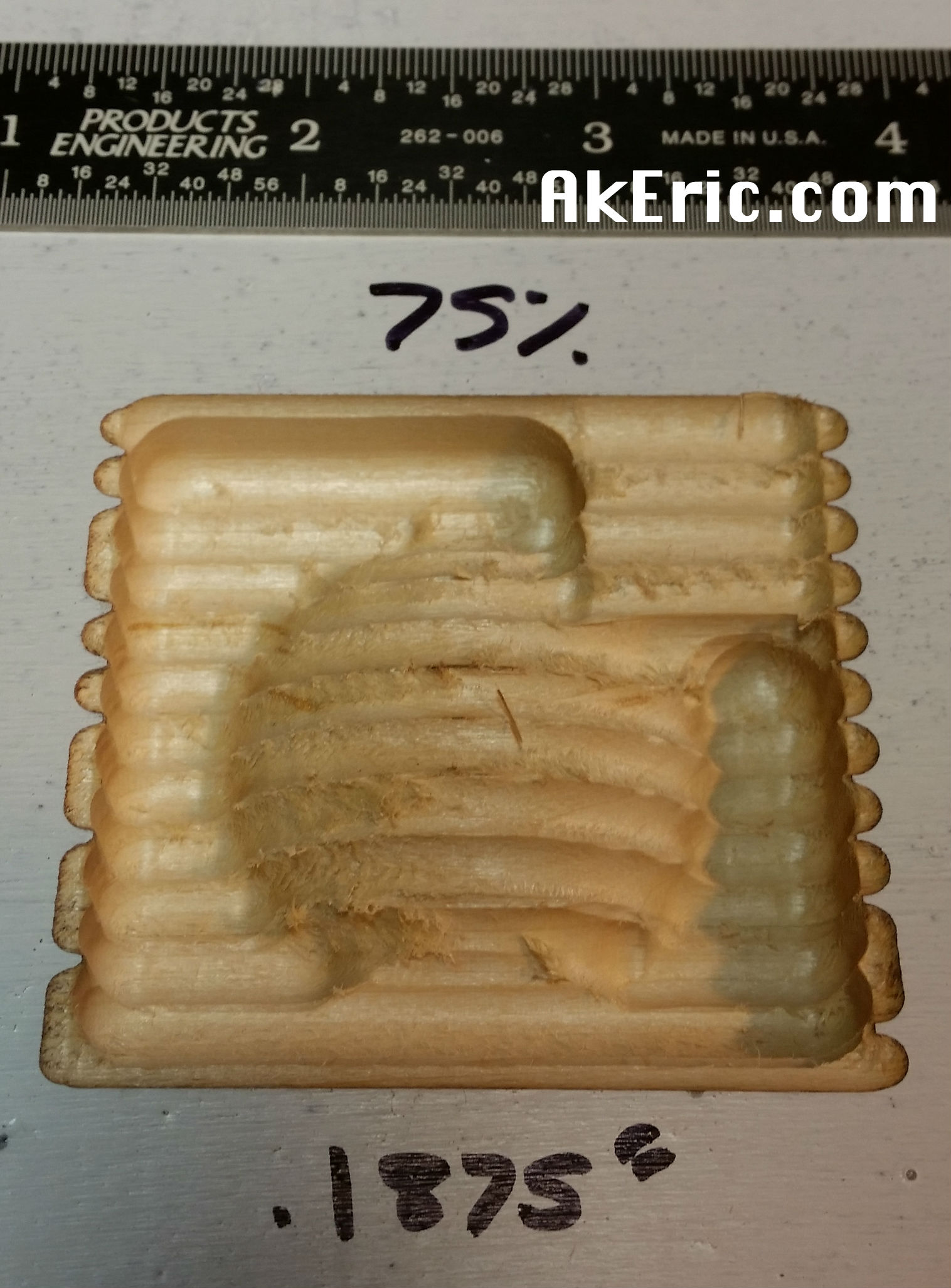
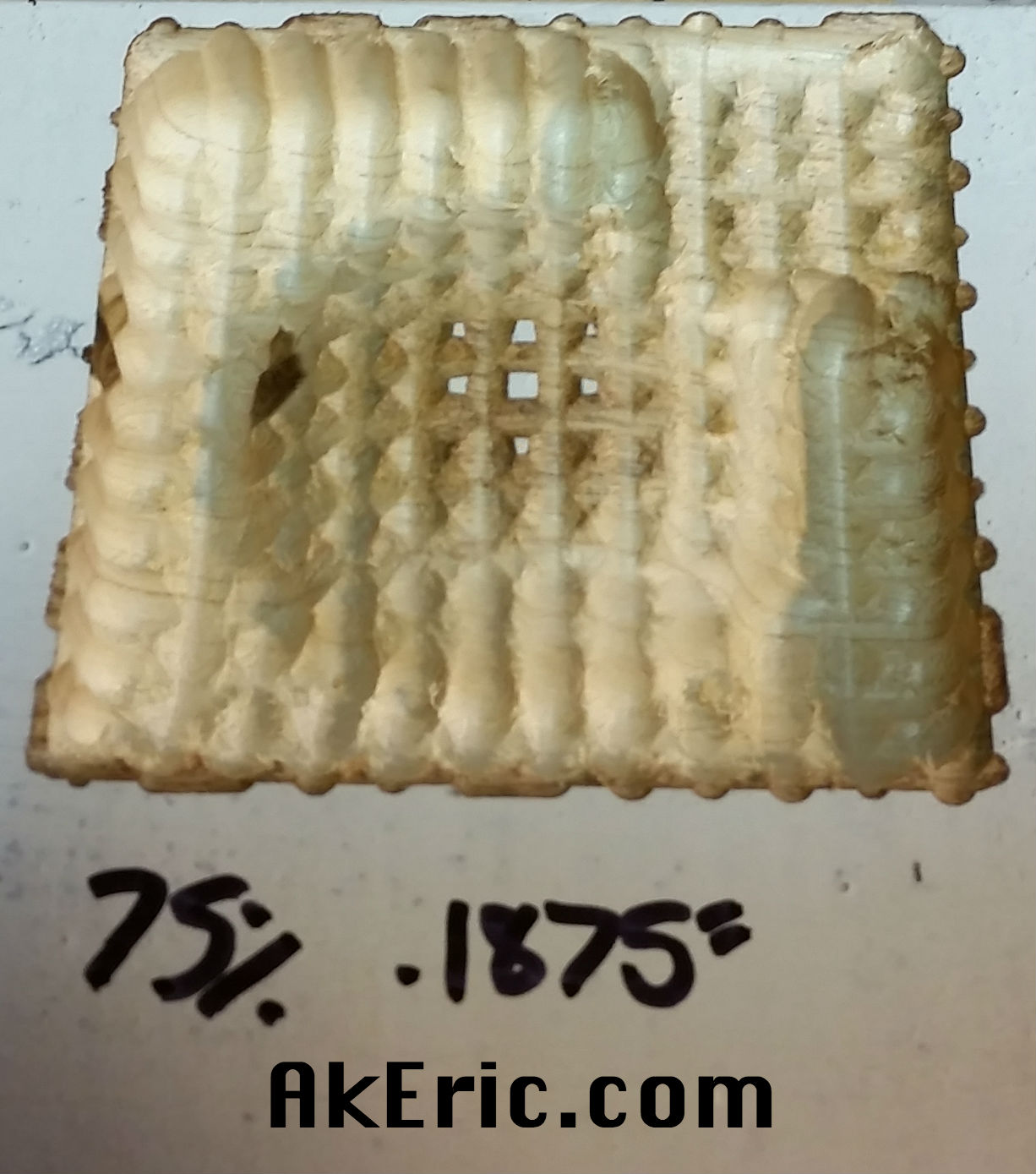
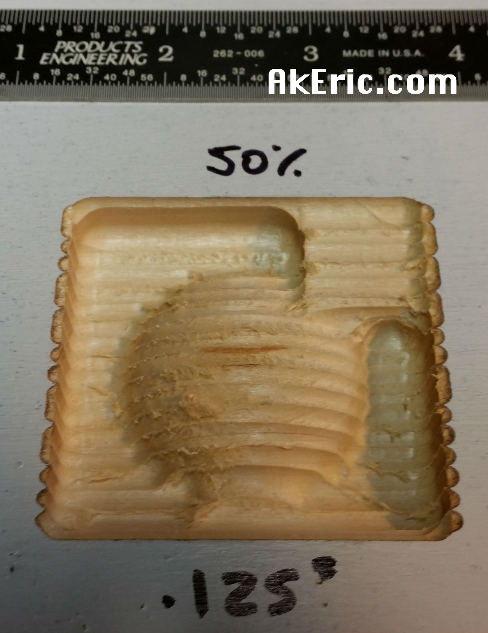
  • Easel has (based on what I’ve experienced) no idea of conventional cuts (bit spinning in the direction of travel) and climb cuts (bit spinning opposite direction of travel).  From what I’ve read, climb cuts can provide better finish, but only on ‘professional\beefy’ machines:  not the X-Carve.  Conventional cuts fare much better on the X-Carve.  This (as I found out) can cause dangerous problems.
  • When the top cut started, it was all conventional cuts, and cut fine.  But when the next layer started, and for every layer down, it was climb cuts.  Because of that, I noticed a lot of bit defection, chattering, and even gouging.  To avoid catastrophe, I had to manually monitor the cut, and really crank up the spindle speed as needed to compensate.
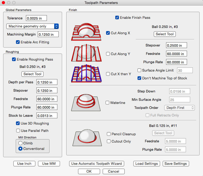
  • Note that MeshCAM gives you the option in the rough-cut to do either conventional or climb cut:  For future aluminum projects I’ll be using it for sure.

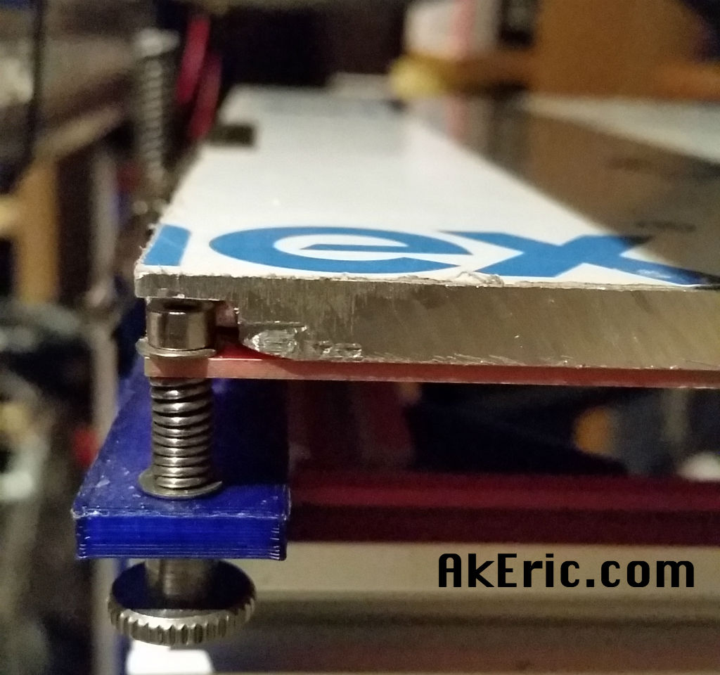
To help with heat transfer (that is only a theory of mine) and to prevent any sort of plate-slip (which is legit), I shoot the bottom of the plate with rubberized undercoating.  I then snipped my thermistor line, soldered barrel-jacks onto either side of it, then taped it into the groove on the bottom of the plate:

bottomFinal

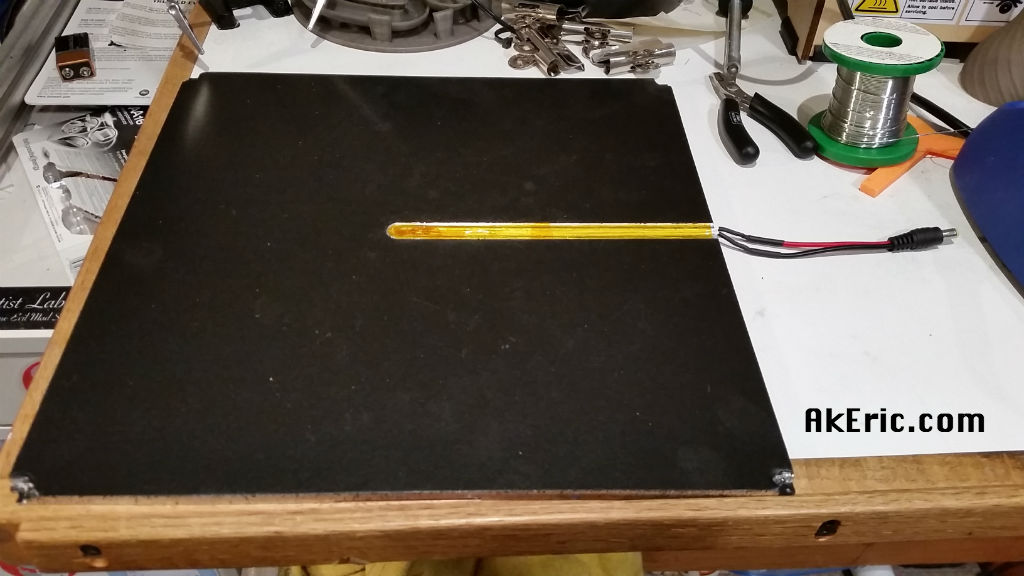
Putting it back onto the HPB, I reconnected the barrel-jacks:

underWiring

Final thoughts

It works, great.

topFinal

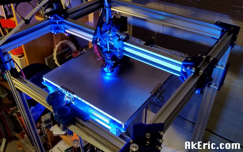
When the HPB heats up, and it finally gets to temp…. it really feels like the top\bottom are the same temp.  And I can level each of the four corners, and the middle is the exact same distance as the rest of them from the toolhead.

Super rewarding project with one machine improving another.


Jump to C-Bot blog index to see all the posts.

Visual comparison of ballnose stepover values on the X-Carve

I built my X-Carve back in December:  It’s been a great new tool to learn.  I’m still very new to the world of CNC, and like to visually grasp the concepts.  So I decided to do a series of tests to understand how ‘stepover’ values effect the finish-pass quality of the surface both on X, and on the XY axes.

The MeshCAM blog does a great job of describing the fundamentals of stepover here.

Here are the stats for the cuts:

  • Hardware:  Inventables 1000mm X-Carve.
  • 1/4″ ballnose bit, 2-flute upcut.
  • Feedrate 60ipm, DeWalt set 1 to 2.
  • Wood type:  Unknown (came from an old bookshelf bottom), but if I had to take a guess, I’d say pine.
  • 3d Design Software: Autodesk Maya
  • CAM: MeshCAM
  • Sender: Chilipeppr

The specifics from MeshCAM below. All values for all cuts were the same except of the stepover, and either “Cut along X”, or “Cut X then Y”.

meshcamSettings_x

I wanted really extreme examples, so I set the following stepover percentages for my test: 100% (1/4″), 75%, 50%, 25%, 10%, 5% (only done on X, not XY).

I started by designing a model in Maya that incorporates a variety of surface angles.  The inside volume is just over 2×2″, by about 1/4″ deep.

stepoverCompare_maya (that’s a flattened sphere in the middle)

I then made multiple different gcode (nc) via MeshCAM, and started cutting them.


The whole piece for the X-cut:

stepoverCompare_all

And the whole piece for the XY cut:

stepoverCompare_allXY (note, no 5% test here)


Individual close-ups below.  X pass on the left, XY on the right.

Note the rough-cut for all pieces took just about exactly 2 minutes.  All the times listed below are for the X & XY-Axis Finish pass in min:sec.  So to get the total cut time, just add two minutes to the below values.


stepoverCompare_100 stepoverCompare_100xy

  • 100% stepover, .25″ : This is obviously super rough.  I honestly expected the segment to be closer together.
  • X Finish Pass Time:  0:47
  • XY Finish Pass Time : 1:34

stepoverCompare_75 stepoverCompare_75xy

  • 75% stepover, .1875″ : Not too much different than 100 really.
  • X Finish Pass time : 1:03
  • XY Finish Pass time : 2:03

stepoverCompare_50 stepoverCompare_50xy

  • 50% stepover, .125″ : Still really rough, but arguably could do something artistic with the ridges at this point.
  • X Finish Pass time: 1:30
  • XY Finish Pass time : 3:00

stepoverCompare_25 stepoverCompare_25xy

  • 25% stepover, .0625″ : Carry on, nothing to see here.  Even with the XY pass, it’s still pretty rough.
  • X Finish Pass time: 2:50
  • XY Finish Pass time : 6:40

stepoverCompare_10 stepoverCompare_10xy

  • 10 % stepover, .025″ : Now we’re getting somewhere: Ridges are still visible, but small.  Pretty smooth to the touch, but you can still make them out.  Sanding could take care of this.
  • X Finish Pass time: 7:10
  • XY Finish Pass time : 14:00

stepoverCompare_05

  • 5% stepover, .0125″ : Done.  Finished.  Can’t make out the ridges with the naked eye.  Very smooth to the touch.  No sanding needed really.
  • X Finish Pass time: 14:20
  • No XY pass done.  Not much point considering the quality already achieved.

Final thoughts:

  • Notice on all X-cuts that the lower-left section of the hemisphere is rough.  Must have to do with the direction of the toolhead (left<>right on X) and the spinning of the bit (clockwise).  The XY cuts removed these issues.
  • If you are ok with sanding, 10%/.025 stepover is ok.  If you want to avoid sanding entirely, go with the 5%/.0125″ stepover.
  • Even though the 5% X-only stepover and  10% XY stepover took the same amount of time, the X-only has a far better surface quality.  You’d still need to sand the 10% XY one.
  • What do I take away the XY Finish pass?  The XY Finish Pass times are generally 2x the X-only times, but don’t really increase the quality.  Not much point unless you’re looking for ‘that look’ in the cuts.
  • I feel like the speeds could be greatly increased on the finish pass:  I was only running the router on speed 1 to 2.  The smaller the stepover, the smaller the amount of material you’re removing, so arguably the faster the toolhead could move to compensate for this under load:  There’s a lot of speed left in the router…. sounds like another good test to try.

New X-Carve project: Soap Dish

Working with the X-Carve has been a lot of fun.  A while back I 3d printed the “Soap Holder by piuLAB“, and figured something similar would be great to route.

Took some time in Maya generating a pleasing voronoi pattern for the top of my soap dish, which I cut out of alder, and the bottom out of some red oak:

soap_wip

Generated the gcode in MeshCAM, and use Chilipeppr to send it to the X-Carve.  Still a lot of learning:

  • For the top:
    • Used a 1/8″ 1-flute upcut endmill at 120″/min, 1/16″doc, 1/16″ stepover, Dewalt611 at 1.5, based on chipload calculators.  It seemed to cut just fine. but as you can see (if you zoom in) there is vertical banding on the Z.  After posting to the forums, the consensus is I’m cutting too fast.  So… I’ll slow it down next time 😉
    • It didn’t cut all the way though, so I had to use an x-acto to cut out the rest of the pockets.  Either I need to trick it into thinking my material is thicker, or do more tuning on my Z-steps.
  • For the bottom:
    • Used a 1/4″ 1-flute upcut endmill at 120″/min, 1/8″doc, 1/8″ stepover, Dewalt611 at about 2, based on chipload calculators.  It seemed to cut just find as well using a conventional climb cut on the rough pass, but on certain sections I got a lot of chugging.  Again, too fast.  Slower next time.

When it was done I applied some stain to the top, and sealant to both, and came up with this:

soap_final

Not too bad all things considered :)

You can download the STL’s from Thingiverse here for routing, or 3d printing.

Digital to wood : A new X-carve piece

New piece I made on the X-Carve:  It measures just under 12″ square, by 1/3″ thick, birch plywood, with some ‘natural’ stain applied:

final_piece

So how did I get there?

Years ago, like ’98-2000-ish, I was really into building shader networks in Maya.  I loved their ramp shader, so versatile.  Later Maya introduced their ‘layered shader’, which is a lot like a layered file in Photoshop.  Over the years my career in CG has taken me away from shader creation, but I always remember how much fun it was ‘back in the day’.

Fast forward to now with the X-Carve :  I know that I can turn a grayscale height-field into mesh, and MeshCAM will turn it into a toolpath, so this was my first attempt at doing just that, via a shader network in Maya:

shader_network

This visualizes (from right to left) the shading group (which the mesh is assigned to) that has both a lambert (just for mesh visualization) and displacement material (for later conversion to displaced polys) assigned.  They’re in turn both fed by a layered texture, that has inputs from a ramp (on top) that defines the border, an ocean texture (that makes the ripples), and another ramp that makes the circles.  I authored a Python script that automates this whole creation process and mesh assignment, with a simple window so I can repeat this process easily.  Iteration is king.

From there, I had something that looked like this, assigned to a flat, tessellated polygonal plane:

heightField

Which I then converted into displaced polygons (Maya: Modify -> Convert ->  Displacement To Polygons)

polygons

Exported as an stl, and brought that into MeshCAM for toolpath generation as a two-part cut:

  • Rough pass with a 1/4″ two-flute upcut endmill.
    • 60 inch/min
    • DOC .0625″
    • Stepover .125″
  • Finish pass with a 1/8″ two-flute upcut ballnose.
    • 60 inch/min
    • DOC .0312″
    • Stepover .025″ : Should have doubled this to get rid of the scalloping.
  • Had the DeWalt 611 router speed set to 1 on both based on rough chipload calculators:  Seemed to do fine, occasionally had some stuttering on the rough pass.

I sent the gcode to the X-Carve via Chilipeppr, and over the next 2.5 hours watched the magic ensue:

finish_pass

The above pic shows the final pass emerging from the rough.

Until the final product appeared:

route_complete

All the hold-downs are overkill, but I realized I had told MesCAM to machine the entire stock, so I had to move them around as the progressed from bottom to top, or I would have machined the clamps themselves.  Noob move.

Pretty happy with the end-result:  It’s actually quite confusing to the eye in person as the shadows dance around it.  Great test though, and a lot learned.

Making The OneHundred

I always found it, humorous, when some Instagrammer got ‘X number’ of people and made some crazy post about it:  “LOVE you all, hugs and kisses”, etc.  I recently hit 100, and figured this would give me a good excuse to combine both my 3d-printing and newfound CNC-routing skills:

I’ve been wanting to do a piece that combined both 3d printing and CNC routing, some came up with idea of a routed background, with 3d printed text.  “The OneHundred” was thus created:

beautyShot

Info on the techniques used to make it:

3D Modeling

The model was created in Autodesk Maya:  I wrote a super simple tool to randomize the rotation and position of simple poly cubes that made up the background.  A 3d model of the text was generated, and Booleaned out of the background.  An stl was generated for both the background, and the text.  The piece is 12″ square, by 3/4″ deep.

3D Printing

The text model was sliced using Simplify3D, and printed on my C-Bot directly off the SD card (I recently was printing something via Octoprint, bumped the RaspberryPi, and it lost USB connection half way through a multi-hour print… don’t like that at all).  Settings:

  • Filament: Makergeeks Orange PLA
  • Extruded @ 230deg (hot for PLA, but per manufacturer recommendation), bed @ 60 deg
  • 1.2mm E3D-v6 Volcano nozzle
  • 600 micron layer heights, 1 shell, 20% fast hexagon infill.
  • Print speed is 45 mm/sec : Sounds slow, but that’s a volume of 32.4 mm3/sec extruded.  For those keeping score, a the volume extruded of a .4mm nozzle with 200 micron layer heights at 90mm/sec is 7.2 mm3/sec:  Volcano is printing 4.5x as fast, crazy.
  • Took about 1.5 hours.  (so, based on the above specs, it would have taken 6.75 hours on a ‘normal’ printer).

CNC-Routing

MeshCAM was used to generate the toolpath cut from the MDF background.  The gcode was sent via the Chilipeppr GRBL workspace.  MeshCAM settings:

  • Roughcut:
    • 1/4″ 2 flute upcut endmill
    • DOC: .0625″
    • Stepover: .125″
    • Feedrate: 60″/minute
    • Took about 1.25 hrs
  • Finish Pass:
    • 1/8″ 2 flute upcut ballnose
    • DOC: .0312″
    • Stepover: .025″
    • Feedrate 60″/minute
    • Took about 3.25 hours

The above settings are completely based on previous trial and error, and could be improved no doubt.  Things I noticed while cutting:

  • Got some chatter on the roughcut, even when I turned up my DeWalt 611 speed all the way.  Guess I was cutting to aggressive.
  • The final piece has more scalloping than I’d like:  Think I need to lessen the stepover next time.
  • Having to babysit the machine for 4.5 hours was… not fun.  But I got to read some magazines I needed to catch up on.

Final Thoughts:

Great learning experience, I’m really getting the two-cut process down using my touchplate.  Can’t wait to do more!