Building the X-Carve CNC Router
Disclaimer: I have no affiliation with Inventables. I’m writing this review purely as my initial experience with this tool.

I’ve been 3D printing for over 3.5 years now, and it’s been an extremely enjoyable hobby: The transition from my virtual work in video-games to tangible objects has been surprisingly fulfilling. Which has lead me to aluminum sand-casting, and I dabble in wood-working in my spare time as well. The more I 3d print, sandcast, and woodwork, the more I want to make… more things, with new methods.
Over the past few years there has been an emergence of desktop CNC machines, and after much research (thanks to Make Magazine, and the internets) I settled on the 1000mm X-Carve kit, by Inventables. It arrived earlier this month, and I’ve been spending a few hours a day putting it together. Finally, on Christmas, I finished it up and made my first cuts.
Why did I choose it?
- Honestly, I really liked how it looked.
- Had the biggest footprint of the popular kits. I don’t know what I want to make yet, but I don’t want to feel limited in a year.
- Amazing online instructions and videos I was able to research ahead of time.
- Active user community in the forums.
- Their CAD/CAM software, Easel. Sort of like CNC training-wheels: I can imagine eventually growing out of this software, but in the beginning it gives you a great, gentle introduction into this world, and was a huge selling point.
- A good collections of projects to start with.
- Entirely Open Source. While I really have no problem with closed-source, I give them kudos for this.
At first I considered doing a series of blogs like when I assembled my C-Bot 3D Printer. But very quickly I realized I don’t think it would have been a value-add to the internet: Inventible (as mentioned above) has amazing online instructions, for which I have very little to add.
Inventables claims you can assemble the whole thing in eight hours: I believe that is possible. While I didn’t time myself, I’m guessing I took around twelve total, really taking my time.
Things that impressed me during the build:
- As mentioned above, the great online instructions and videos. It assembled exactly as described.
- Packaging of all the parts: Everything was individually bagged with a serial number, making it easy to confirm I’d collected the correct parts for each step.
- Nothing missing: Every piece accounted for (but a single damaged nut, see below).
General Gotchas:
- One nylon lock-nut was damaged. Looks like during manufacturing it got squished beyond usability, and was missing its nylon insert. Since they give you exactly the number of parts you need, I ended up one nut short. Luckily my parts bin had something that worked.
- If you use a router like the DeWalt 611 that has ‘manual spindle control’ (I didn’t even know what that meant until building this), but ordered the wire for ‘automatic spindle control’, you can get confused, if you’re a noob like me: Since the overall instructions are done so well, when something doesn’t make sense (what is this wire for? How do I hook it to my router?), it’s actually even more confusing because you think you’re missing something. In this case no, I wasn’t missing anything, the instructions just presume you know a bit more in this area than I did.
- While you can order a toolkit with it (which I did not do), nowhere I can find do they list the tools you need. For example, you’ll need a soldering iron, to do some (pretty simply) solders. I can imagine that if you’ve never soldered anything before, this may cause anxiety. Plus you need a number of metric hex-wrenches, a carpenters square, etc, etc. A tool-list would be nice. Maybe I’m just missing it…?
- No dust-shoe. I find it surprising they don’t provide one (for purchase), considering how much dust this thing makes. There are a multitude of DIY ones the forums though, and will be one of the first things I build to accompany it.
- In Easel, I have yet to find a way to manually jog the steppers, other than going through the “Set up you machine” phase. In the 3d printing world, manual stepper control is pretty commonplace to help move the toolhead around the bed. Maybe I’m missing this too?
- The top of the DeWalt 611 router hits the top of the Z-assembly, near where the leadscrew affixes to its belt. Reading the forums people claim you can turn it to move the colliding bits out of the way. I was unable to achieve this, and used my belt-sander to grind off a good 1/8″ of plastic and metal. Problem solved, but seems a bit clunky.
- The shipping cost of the 1000mm wasteboard is crazy (That sized wasteboard + hardware is $128, and the shipping is more than that). Being a CNC noob, I didn’t know how important it was to get that wasteboard, are all those holes needed, etc? Because of that, I ended up ‘just getting it’ (thanks to a $100 off special before Christmas, which I mentally ‘applied to shipping’). They do provide the cad files online (being open source and all) so you can make your own, presuming you have access to a… CNC router. And there is discussion on the forum over wastebord options, but it’s a bit scattered, and not entirely clear to a new user. I think if Inventables provided a way to manually build your own wasteboard using say, a table-saw or circular-saw and some MDF, it’d go a long way to attracting new users that couldn’t afford the shipping. Are all those holes needed? No. But they are handy.
First Cut:
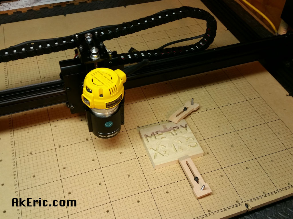
After the machine was assembled and I ran through their Easel tutorial, I created my own “Merry Xmas”/snowflake combo (shown above). Affixed a 5.5″ x 5″ x .75″ block of scrap wood to the wasteboard, installed my 1/8” dual-flute ball end (which as it turns out, is the smallest bit I ended up buying), and started cutting.
Thoughts:
- Cutting seemed slow (based on my CNC Experience Level 1). I have a feeling the software was just being safe using the defaults.
- I’m still learning Easel, and got the order of the snowflake and text wrong, so the snowflake blocked the text, rather than the text cutting the snowflake. Live and learn.
- All things considered, super simple to do.
- I need to get a dust-shoe setup.
Final Thoughts:
Overall, I give this build and initial use a solid A. Far less work than my C-Bot build (which admittedly was muuuuch more DIY). I really look forward to learning the world of CNC, and how it can compliment my 3D printing.
