Exporting usable CAD data from Maya
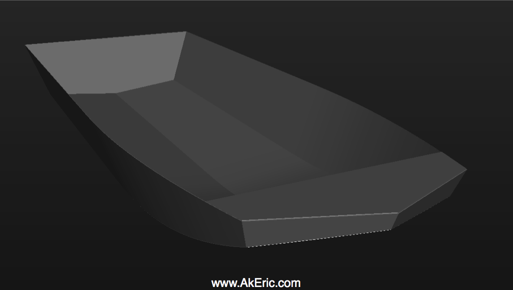
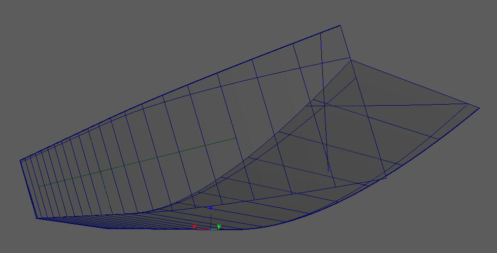
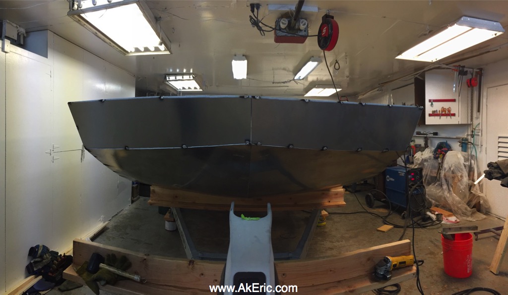
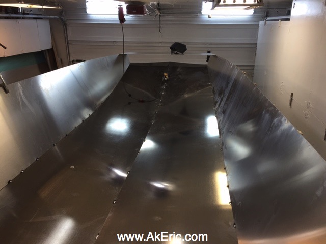
It’s that time of year again: Time to help my father build a new aluminum boat. It was an enjoyable process last year: Based on a napkin sketch with some dimensions and angles he gave me, I modeled a boat out of NURBS in Maya, and through a lot of hoop-jumping, got him some useable data:
The biggest hurdle was getting him ‘the usable data’. The process of making the boat in Maya is discussed above. But these were the export steps:
- Export the mesh from Maya as obj.
- Use online converter to go from obj -> pdf.
- Then, my father gave the pdf to a buddy who traced it in CAD, gave it dimensions, then provided that to the plasma-cutter (as a DWG).
- Ugh.
That process was super clunky. I’ve been using Maya since… 1998(?) and never once needed to export anything CAD related, so this was all new territory. To make this work I need a way to generate the CAD data myself, add dimensions to it, and export out as a DWG. There must be a better way!
Turns out there is (and probably even a super-moar-better way than what I’m about to describe, if you know CAD better than I do, which wouldn’t be much of a stretch). In the back of my head I remembered that Maya has a DXF exporter. I don’t think I’ve ever once used it…
Part 1: Get CAD Software & Configure
Since this process is (currently) a once-a-year thing, I didn’t want to drop a bunch of cash (any really) to get some newfangled CAD software. I’d read a lot about FreeCAD on the interwebs, it was available for Mac, so I installed it.
Fumbling around however, I realized it neither could import DXF, or export DWG, by default.
To get the DXF importer\exporter working, I followed the instructions here.
I never could actually get the DWG export working from the software, even following the instructions here. However, that links to a standalone “Teigha File Converter” that will batch convert a directory of DXF files to DWG. Good enough.
Also, this data needed to be in inches, so I changed the FreeCAD prefs as such.
Part 2: Export usable CAD data from Maya
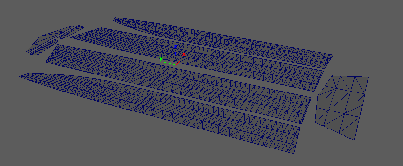
I started by exporting the unrolled mesh as DXF from Maya: There are zero options available. But FreeCAD happily imported it. Immediately, problems: Missing triangles (you must exported triangulated mesh, can’t have quads\n-gons). As a check, I exported this same data out as DXF, and reimported it: Empty. I don’t think FreeCAD likes to deal with polygonal mesh.
Next, I tried exporting the unrolled NURBS surfaces as DXF: Those came in as empty groups in FreeCAD…
Finally, I converted the trimmed NURBS to their perimeter curves, and exported the curves: Success! This is what is important to know:
Export NURBS Curves from Maya as usable CAD data.
Polygonal Mesh = highly questionable. NURBS Surfaces = no go. Note I also tested locators & ‘distanceDimShape’ nodes: They don’t export at all.
Once I had the boat’s unrolled\flattened curves in FreeCAD, I started adding draft dimensions. Where I encountered my next problems:
- The scale was off by a factor of 10: Even though Maya was set to inches, and FreeCAD was set to inches, everything was 10x as small in FreeCAD. I noticed this is the same issue when I 3d print in cm: Even though I have Maya in cm, and my slicer (Simplify3D) is in cm, they come in 10x smaller. The fix? Scale everything up in Maya 10x before export.
- From the top view in FreeCAD, all the curves looked just like Maya. But when I went into a perspective view, the curves were actually going shooting up & down in space quite a bit: Not on a flat plane. But they are in a flat plane in Maya. What’s going on? Long story short: In Maya after you do the 10x scale up, be sure to ‘freeze transformations’ on all the curves. In addition to the scale, I had many other translate and rotate values on the curves to get them flat on the ground plate. It appears that FreeCAD hates this. But once everything was frozen, the curves showed up a-ok, from all angles.
Note: Maya uses the Autodesk ‘DirectConnect’ file translators to export (and import) DXF data. See the docs on the 2016 version in this pdf.
Part 3 : Add Draft Dimensions
Since I was told that this needed to be provided to the plasma cutter in inches, in FreeCAD’s ‘General -> Units’ prefs, I’d set them to “US customary (in/lb)”. Next, via FreeCAD’s ‘Draft’ toolbox, I used the ‘Dimension’ tool to provide width & height values for all the curves. This is where I ran into the next (and as of this authoring, unresolved) issue: FreeCAD seems to auto-change the what unit is displayed in the dimension based on the length of the part being measured. For example, I want all the dimensions to be in inches. But they’d report inches, feet, and yards, depending on the length of the part. After posting this issue to the forums, I learned that if you switch the units to “Imperial decimal (in\lb)” the dimensions will always be in inch. Problem solved. Thanks forum peoples!
Part 4 : Export
From FreeCAD, I export all the curves and dimensions as DXF, then using the Teigha File Converter, convert that to DWG.
And…. done? Still need confirm from the plasma cutter the DWG is valid (I have no way of testing myself), but overall, a far less clunky data-export-pipeline than last time