Posts Tagged ‘ Autodesk Fusion 360

Designing a 3d printed smartphone case

I recently picked up a new Samsung Galaxy S5, and needed a case for it.  I’d previously printed cases for my wife’s iPhone (here) based on a Thingiverse app.   But there were no apps I could find for the S5, so I decided to make a case myself.  Below I discuss at a high level the steps I went through.

Decide the authoring software

While I’m intimately familiar with Autodesk Maya, it’s not really geared towards highly-accurate solid modeling.  Considering I wanted to do this on the cheap, that limited me software-wise.  My main choices were Autodesk 123D Design, and Autodesk Fusion 360 (suggestions from anyone else?).  While 123D Design could probably do it, I really liked Fusion 360’s timeline based workflow/history, and overall it is a much more powerful tool (but costs $ if you want to use longer than a month).

Specific things I learned about Fusion 360 on the Mac:

  • FYI I’m still very new to the software, so it’s quite possible I could be missing something when it comes to my below presumptions.
  • The ‘Sketch -> Project/Include’ menu is confusing.  But it’s where you go if you want to either project curves onto a surface, or when authoring a new sketch include 3d geometry to use as reference.  The docs on it are greatly lacking.
    • If you want to include a surface as reference, select the surface, then access that menu:  It will create a new sketch with the surface as reference.
    • If you want to project an existing sketch onto another surface, it looks like there’s a bug on the mac.  I discuss the bug, and the solution on the forums here.
  • It’s better to add features via the Modify & Create menus than the Sketch menu:  Modify & Create features are added as history to the timeline, while making changes to a sketch aren’t recorded in history.  For example, if you need to apply a fillet, you can fillet a sketch (which is then extruded into a surface), or you can fillet the surface after extrusion.  Filleting the surface (rather than the sketch) seems to be a better call if you later want to change the fillet values.
  • I had a hard time figuring out how to accurately place sketches relative to ‘something else’ (like placing a circle exactly 17mm away from an edge).  It appears the workflow goes:  Make your sketch ‘somewhere’.  Then, using the ‘Sketch -> Sketch Dimensions’ tool, create relationships between your sketch and the ‘something else’ based on distance.
  • Running it on a Macbook Air probably isn’t the best choice:  Not very responsive, pretty chuggy.

Find a starting point

I first downloaded and printed this design from Thingiverse.  In fact my original plan was to print that case and be done with it.  But that case has a large clip that rubs right against my ear, and got painful on any call over 30 seconds.  That is really what prompted me to design my own.  While I could have used that case as a starting point, I wanted this design to be ‘all my own’, so my usage of it stopped there.

To get started I simply traced the phone on graph paper, then using my calipers measured all applicable distances for buttons and doodads:

graphPaper

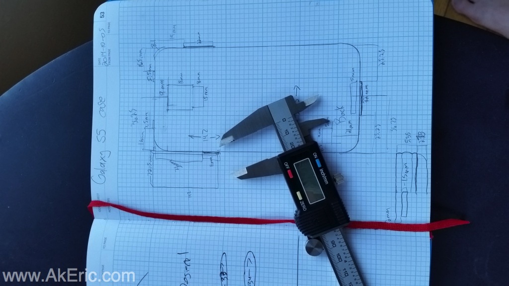
This gave me what I needed to begin authoring in the software.

Iterate on design

It’s crazy to think that what I’m effectively doing is iterative product design.  The ability for me to model something in 3d, and have a printed version an hour and a half later (for about 1$) is just amazing.  Over the course of several days I slowly refined my design, print after print.  Some days I’d iterate and print 3 designs.  Here’s the evolution:
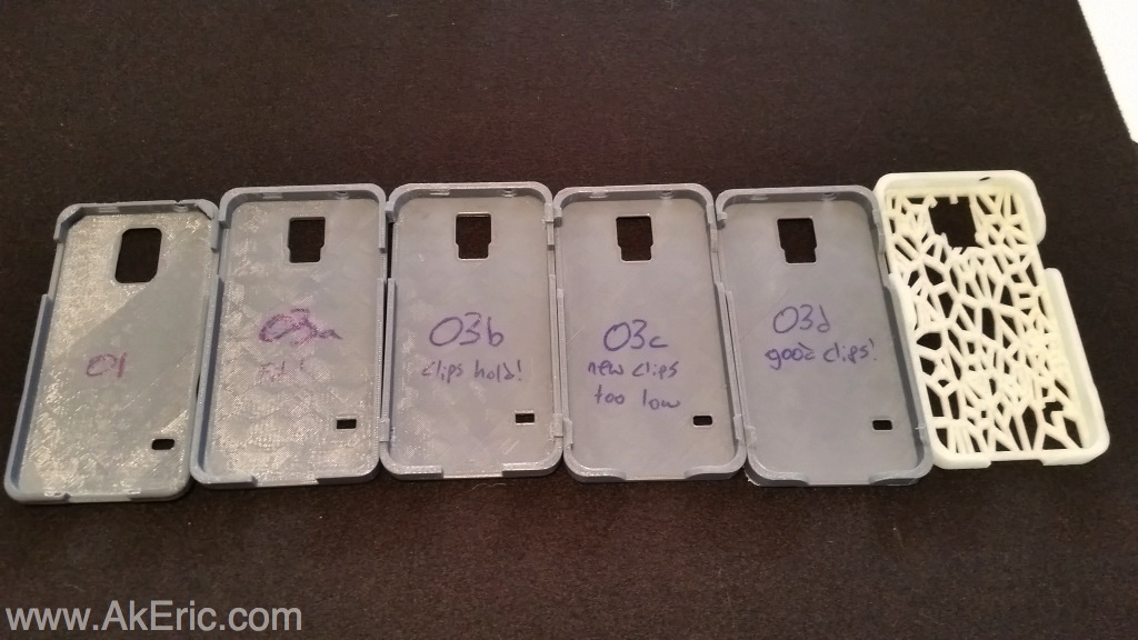
phoneEvolution

From left to right:

  • 01 : My first attempt.  Had clips to hold the phone in on the top corners, and the bottom by the plug.  Failed not being deep enough, and the clips required print supports that weren’t generated, so their undersides bowed down blocking the phone.
  • 02 (not pictured, never printed) : Trying to fix 01.  Realized the way I modeled in prevented me from modifying it in a procedural way (still learning best practices of the software).  Whole design scrapped.
  • 03a :  Complete re-design.  Before I modeled the case, I modeled the phone to spec.  This allowed me to compare the 3d phone to the 3d case to make sure everything lined up.  03a had no top clips:  It’s just the base, sides, and required holes.  I wanted to make sure I had designed something that would fit the phone before I put any more effort into the details.  Note I made the case half a mm taller and wider than the phone, and it seemed to fit perfectly.
  • 03b : Creation of top clips to hold the phone in. These are simple cubes on the top L/R and bottom L/R sides.  While the phone fit and clipped in, the clips themselves required support material which was hard to remove.
  • 03c: New clip design that added a chamfer under them to provide print support, and on top to ‘soften’ them so they wouldn’t hook things, like my pocket.  Unfortunately the chamfer hit the top of the phone, and it didn’t fit well.  Also added rounding to the sides where they come close to buttons, to allow more room for fingers.
  • 03d:  Changed clip design again:  Raised the under-chamfer up:  Phone fits well!  But after using it for a day I found two more problems:  The top left clip (by volume control) was small and would get hooked on my jeans (and eventually started to split the case apart) since it was so square and sharp on one side.  In addition, even though there was plenty of clearance for my fingers from the top, the base of the case was actually in the way when trying to push the side buttons:  The base needed cut out near the buttons.
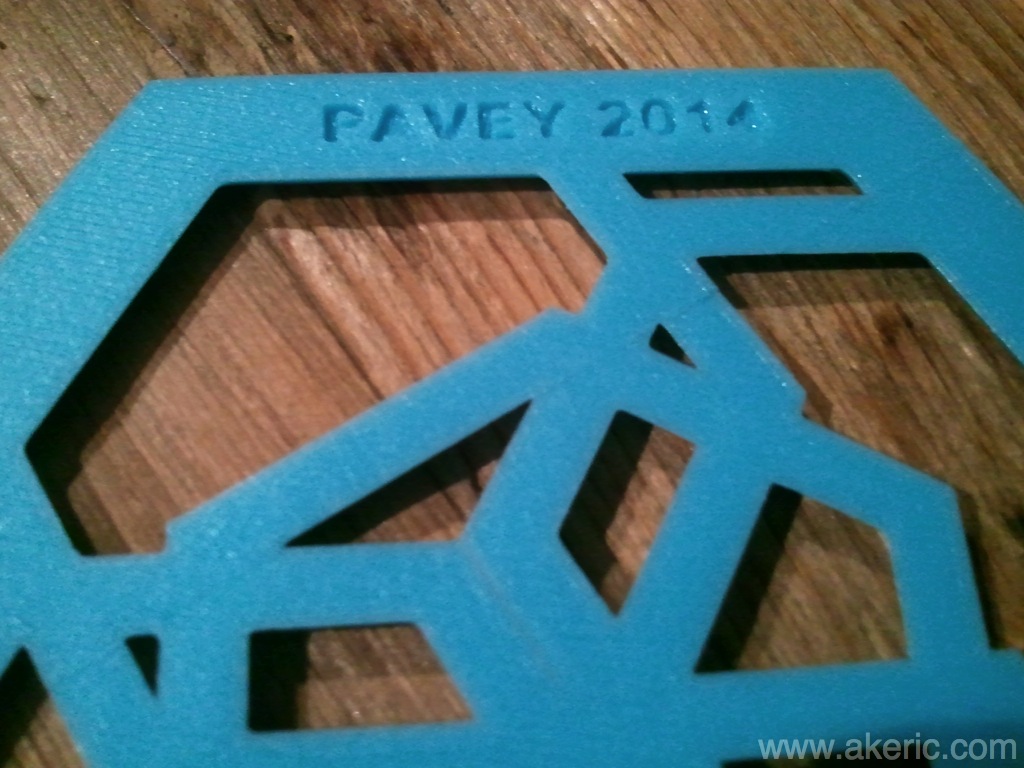
  • 03e (white case) : I went ahead and arted this one up thinking it’d be the final design, but not quite:  I added notches in the base at the volume, power, and usb port:  Much better finger clearance now.  Added in my logo as embossed text on the left side.  I again completely redesigned the clip on the left side:  Rather than the two on the top\bottom left, I made a single larger one in the middle left:  No longer catches on my pants.  But human trials revealed one last problem:  I never applied a fillet to any edges of the frame.  All the new “notched in” sections actually had quite sharp corners.
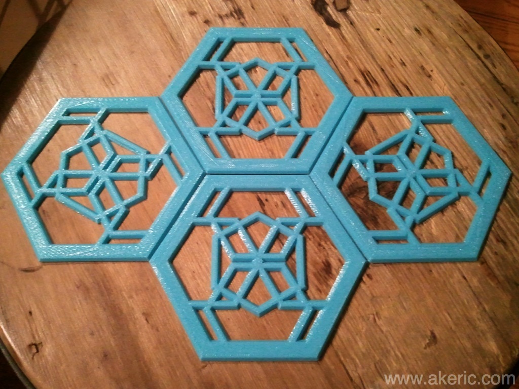
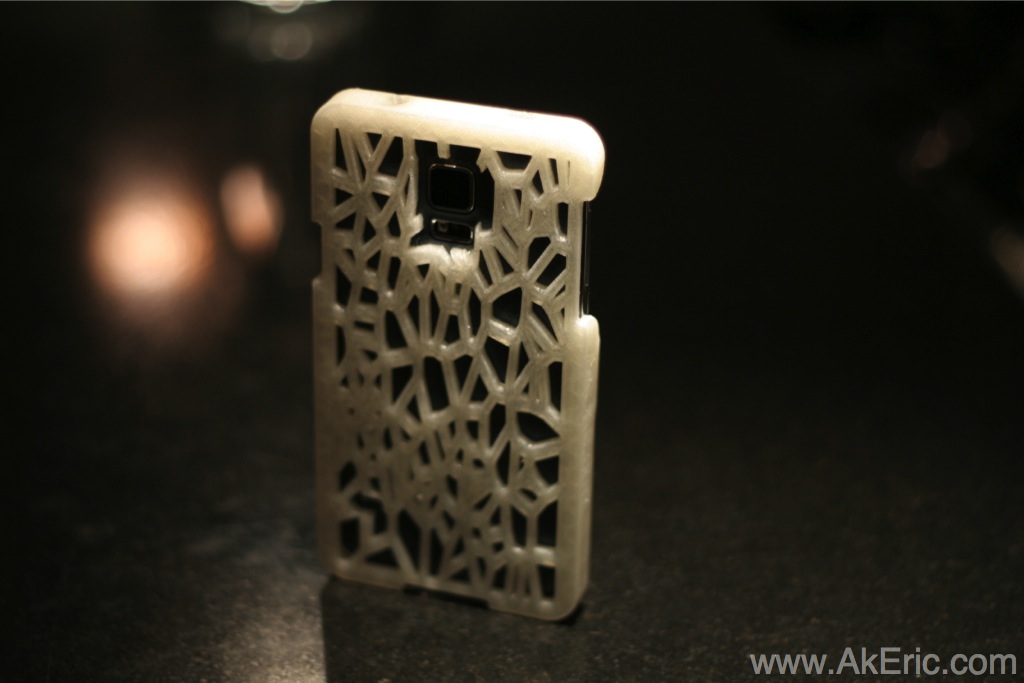
  • 03f (final case, shown on top of post) : Applied a nice fillet to all exposed edges rounding them off, and making less pointy.  Arted up thanks to the Voronoi tool and a quick boolean in Tinkercad.

Here’s a shot of the final design in Fusion 360 before art/print:

screenshot

And in Tinkercad, adding the Voronoi boolean:

tinkercad

Final version was printed (about 2.5 hours) on my Makerbot Replicator 1 with these settings:

  • Natural PLA extruded @ 230 deg c.
  • Removable glass build platform covered with glue-stick (first time trying it, works great!).  Heated platform off.
  • 200 micron, 2 shells, 15% infill, no supports, no raft.
  • Final weight, 30g.  Which works out to about $1.05 of material.

Really enjoyable, fulfilling experience to know I have a completely custom, one-of-a-kind case I designed from start to finish.

Purchase:

If you have interested in one, I’d be happy to print one for you.  Please access my 3D Hub and place an order:  They’re $24.21 each, + tax & shipping.

HexTrivet

Based on my previous post of comparing different 3d apps for 3d printing, I thought I’d give Autodesk Fusion 360 a shot at making a simple hexagonal “trivet”:  My goal is to try to eventually cast this in aluminum, to see how well the small structures work.  But in the mean-time, things I learned:

  • How to create exacting-sized objects in the software:  It’s 100mm wide, and 5mm tall.
  • How to create my name & author year, and boolean that into the base of the solid.

Each trivet takes about an hour to print on my Makerbot Replicator (1), at 200 micron, with 2 shells, and 10% infill, using light blue PLA.  Took maybe… 20 minutes model?

SAMSUNGSAMSUNG

3d Modeling Apps: Comparing Features

I wanted to compare some standard features needed for creating 3d models in regards to 3D printing.  While I’m well versed with Autodesk Maya, I’m always interested in other (free) option for more simple things.  I’m not expert at any of these:  If any info I’ve presented is wrong, or you know a better way, please comment.

My test was done on a Macbook Air, Chrome web browser.

The apps compared were Autodesk Fusion 360, Autodesk 123D Design, Tinkercad, & Clara.io

The features I’ll compare below are:

  • Boolean operations
  • Text creation
  • STL export
  • SVG import

Results:

Autodesk Fusion 360:

  • Overall thoughts:  The most powerful when it comes to solid model design.   Just wish I could get svg import working.  I feel like I’ve only scratched the surface.  I wish it ran better on my Macbook Air:  Lots of crashing/graphics glitching.
  • Boolean Test : Success
  • Text Test : Success
  • Bonus Test : Success
  • SVG Import : Fail
  • STL Export : Success

Autodesk 123D Design:

  • Over Thoughts:  Mixed bag… a weird split of features between the web and computer app.  I had a hard time with the user interaction.
  • Boolean Test : Success
  • Text Test : Update : Success (old was Mixed)
  • Bonus Test : Web App Fail, Desktop App Success
  • SVG Import : Success
  • STL Export : Web App Fail, Desktop App Success

Clara.IO:

  • Overall Thoughts:  Feels like “Maya Light” (which is a good thing) : Will be interested to see what direction this software takes in the future.  Not really designed for solid modeling, but I thought I’d give it a shot to see what features it has in this area.
  • Boolean Test : Fail
  • Text Test : Mixed
  • Bonus Test : None/Fail
  • SVG Import : Fail
  • STL Export : Success

Tinkercad:

  • Overall Thoughts:  Had the most fun with this one : While it has the most limited option for making custom geometry in the software, once you imported geometry it was fast and flexible.
  • Boolean Test : Success
  • Text Test : Mixed
  • Bonus Test : Success
  • SVG Import : Success
  • STL Export : Success

Detailed Results:

————————————————————————–

http://fusion360.autodesk.com/

Boolean Test:

Create two mesh, overlap slightly, union together.

Result:  Success :  When creating new objects they will auto boolean if they overlap, nice feature.

Text Test:

Create text, change the font, apply a bevel/chamfer.

There is a Sketch -> Text menu that will create text as curves.  After creation while selected you can access the Create -> Extrude menu to pull it into a shape.  Video on YouTube showing off more complex stuff.

Pros:

  • Easy to implement.
  • Huge selection of fonts.
  • History allows for changing of font after creation.
  • Easy to select top-faces for chamfer operation.

Cons:

  • None, other than sluggish on my 4 year old Macbook Air.

Result : Success

Bonus Test:  Boolean Text

Using the above text and already-booleaned surfaces, I was able to successfully do a boolean subtraction of the text from the solids via the ‘Modify -> Combine’ menu, then changing the option to “Cut”

Result : Success

SVG Import:

There is a Sketch -> Import SVG menu.  However whenever I’d import one, nothing would show up.  Finally, but using the “Find In Window” option I could get it to show up, but the I would loose control of the camera, and software:  My guess is either it was infinitely small or big, causing a problem.  I tried SVG’s made from multiple different software, experienced the same problem :S

Result : Fail

STL Export

You can RMB on any “Body”, and access a “Export as STL” option.

Result: Success

————————————————————————–

http://www.123dapp.com/design

There are two versions:  One on the web, and a desktop App.  Where noted below, I used the Mac desktop version.

Boolean test:

Desktop Version : Create two mesh, overlap slightly, union together.

Result : Success : The ‘Combine -> Merge’ boolean operation worked without a problem.  That being said, I found the user-interaction aspect of picking the objects in the correct order surprisingly confusing.  I would repeatedly do it wrong.  I also found it clunky trying to access the old shapes for modification.

Bonus test:  Subtract the results of the torus-union boolean from a cube.

Result : Success : Very clean subtraction result via ‘Combine -> Subtract’.

Text test:

Create text, change the font, apply a bevel/chafer.

Desktop version:  Success (Updated) : When I initially reviewed this, there was zero desktop text support.  As of this update there is a very large font library available.

Web App:  Pressing the “T” button creates some default text you can place on the ground plane.

Pros:

  • Easy to create / change size.
  • Easy to change text once created.
  • Desktop has a very robust font selection.  Web has seven different fonts to choose from (if that’s a ‘pro’?).

Cons:

  • Selecting the edges for the chamfer operation is very tedious.
  • When I finally selected all the edges needed and chamfered them, it crashed the app.
  • Trying a chamfer again worked, but this time I did the inside/outside of the “O” apart from one another.
  • Once chamfer is added, unable to go back and change font/text.

Results: Success : But need easier way to select font edges for chamfer operation.

Bonus Test:  Boolean Text

  • Web App: Fail : I was going to try this, but the web-app quit responding.  When it finally did return, the “Primitives” menu would load.
  • Desktop App: Success : Since I’d already made text in the web-app, I was able to open that project in the desktop app and successfully to a boolean-subtraction from a cube.

SVG Import:

Has a native “Import SVG…” menu option.

Authored both some text and a scribble in Inkscape:  Was able to import the scribble, but not that text.  But seeing that other software had the same problem, I’m thinking Inkscape is exporting bad font SVG files.

Result : Success

STL Export:

Web App:

  • Result : Fail : Have options to ‘Send To -> 123D Make’ (which I don’t have installed) & ‘3D Print at home’ which gave me an error.

Desktop App:

  • Result : Success :
    • Has a “Export to STL” option
    • Also has an option to “3D Print”, which opens the Meshmixer app, presuming you have it installed.  Meshmixer has a stl export as well.

————————————————————————–

https://clara.io

Boolean test:

Create two mesh, overlap slightly,  union  together.

Result :  Fail : clara.io’s ‘Model -> Boolean’ operations are listed as ‘Experimental’, and based on this simple test, it is a fail:  Even though the mesh are simple low-poly objects, no matter how I align them, I get a “Maximum call stack size exceeded (Operator Error: Boolean (Create))” error.

Text test:

Create text, change the font, apply a bevel/chafer.

Create -> Polymesh -> Text

Pros:

  • Easy to create / change size
  • Easy to change the text once created.
  • Easy to create bevel via Text-shape’s ‘bevel’ option.

Cons:

  • Only one font option: “Helvetiker”.  Checking the webs/forums, other people have been asking for more font types.

Result : Mixed : Needs more font options.

SVG Import :

Result : Fail : Doesn’t appear to support svg files.  Google searching didin’t turn anything up, and browsing the software itself didn’t show any type of NURBS / path tools : Looks like polygons only.

STL Export:

Result : Success : Has option to ‘File -> Export Selected -> STL’.

————————————————————————–

https://www.tinkercad.com

Tinkercad could be considered 123D Design Light.  But it does things better.  Also, it was the fastest performing software out of all tested.

Boolean Test:

Create two mesh, overlap slightly, union together.

Result : Success : Surprisingly easy to do (once you understand it) : You simply “group” the two objects.  They’re now ‘unioned’ together.  If you want to do a subtraction, change one of their colors to “hole”.  All history is maintained, and it’s easy to access the old shapes to tweak them.

Bonus test:  Subtract the results of the torus-union boolean from a cube.

Result : Success : Very clean subtraction results:  Both torus are set to ‘hole’, and grouped with the cube.

Text Test:

Create text, change the font, apply a bevel/chafer.

Basic Text Test:

  • Authoring basic text in Tinkercad is pretty painful:
    • There’s no font/text tool.
    • You have to drag in individual pre-created letters.
    • All caps, all the same font.
    • All have to be individual resized/shaped.
  • Overall fail.

Shape Generator Text:

  • Tinkercad has a “Shape Generator” tool that is actually quite robust.
  • You execute a “New Shape Generator”, and select “Text”.
  • The default gizmo has options for 3 fonts.  But if you “Edit” the tools source, you can access the JavaScript directly, and see where they’ve plugged in the fonts provided:  If you have your own svg font, you can upload it and edit the source to include it.
  • I was able to install a custom font by following these steps:
    • Found a font I liked from Fontsquirrel, and download it.
    • Go to their font generator page, Set the mode to “Expert”, then set the export format to SVG (only) : Down load your kit.
    • This gives you a zip you can extract.  Then back in Tinkercad you “Edit” your Text Shape Generator, and follow the instructions towards the top of the main.js script for installing the new font.
    • Success!  Sort of:  The app kept giving me a warning, but everything seemed to work.
  • Overall : Mixed : While it gives you the ability to add new custom fonts (which none of the others appear to provide) you still can’t bevel/chamfer them.

Bonus Test :

I booleaned all sorts of text and shapes together.  Super easy.

Result : Success.

SVG Import:

Tinkercad has a Import menu that allows you to browse to a svg on your HD, or from a URL.  Example video on YouTube.

Authored both some text and a scribble in Inkscape:  Was able to import the scribble, but not that text.  But seeing that other software had the same problem, I’m thinking Inkscape is exporting bad font SVG files.

Result: Success

STL Export:

Result: Success : Very to export via the ‘Design -> Download for 3D printing’.  Note this downloads the entire scene.