3D Printer Surgery: Replacing my Makerbot Replicator 1’s Voltage Regulator
I purchased my Makerbot Replicator (1) when they were first released, nearly 3 years ago now. Other than a few hiccups (HBP cable failing repeatedly, and a dead botstep needing replaced) it’s ran like a champ. Reading the forums like I do, I’ve seen a number of people talk about their voltage regulators dying (the LM1084), and killing the whole board in the process. I don’t know when I’m going to upgrade, and I’d like to keep this machine running as long as possible, so an update was in order.
Makerbot users are always a super-helpful bunch, and the folks over at the Makerbot Users Google Group are no exception. I’d seen a lot of posts on the subject, but none that really broke down specifically what needed to be done, and what parts needed to be sourced. So I asked, and they answered. Armed with that knowledge (and this great photoset by JetGuy) I ordered from Digikey a “Recom Power R-78E5.0-0.5” voltage regulator (the 5v version, not 3.3v) based on user tramalot’s recommendation. Below are the overall steps I took to install it. It’s not hard once you grasp what needs done, and my hope is this breakdown can help others in the same situation.
First I sketched out the old and new wiring on paper: The new regulator has a different pinout: Everything has been shifted one pin left.
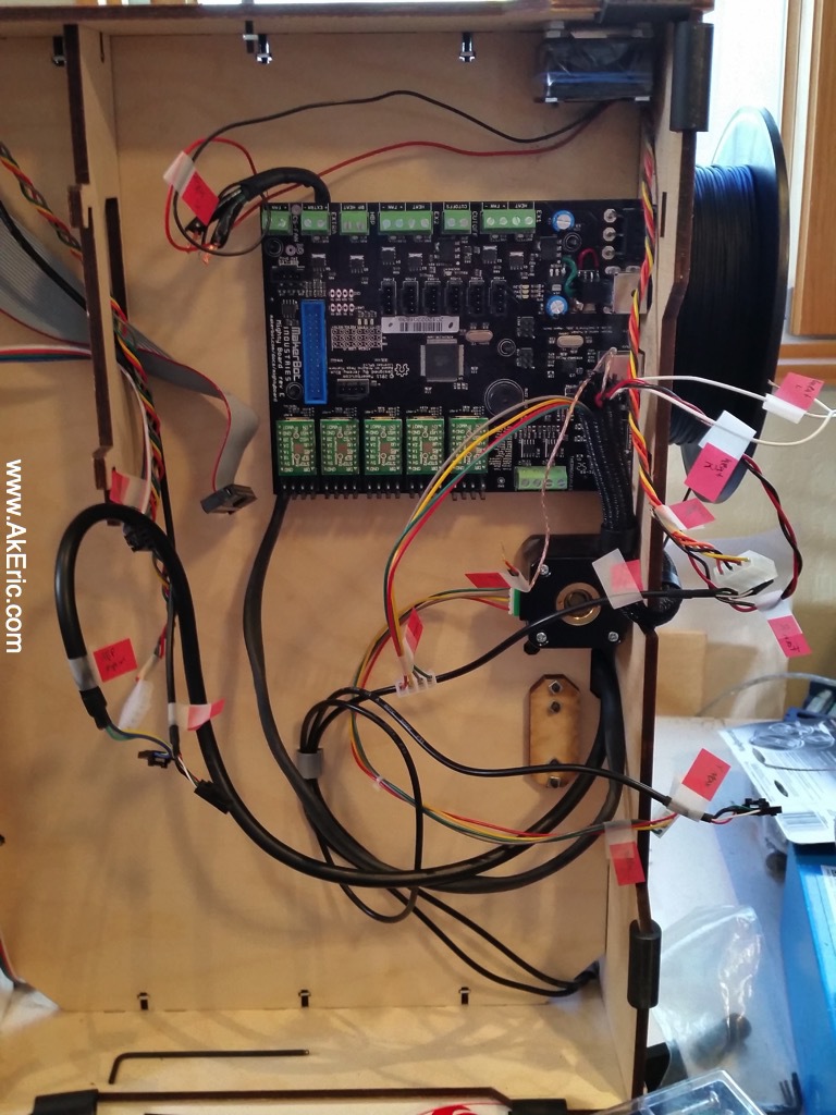
Next I snapped a pic of the Mightyboard pre-removal as a sanity check:
I made sure to ground myself with a wrist-strap just to be safe.
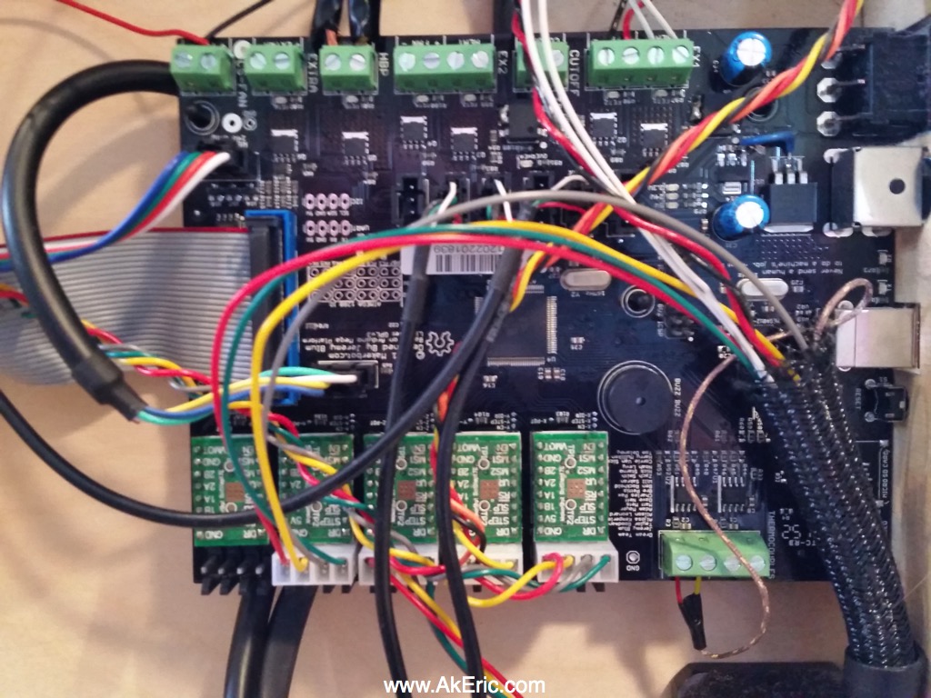
I then labeled all the wires with little stickies, unhooked everything…
 (note, this is actually the board on reinstall, but it’s all the same)
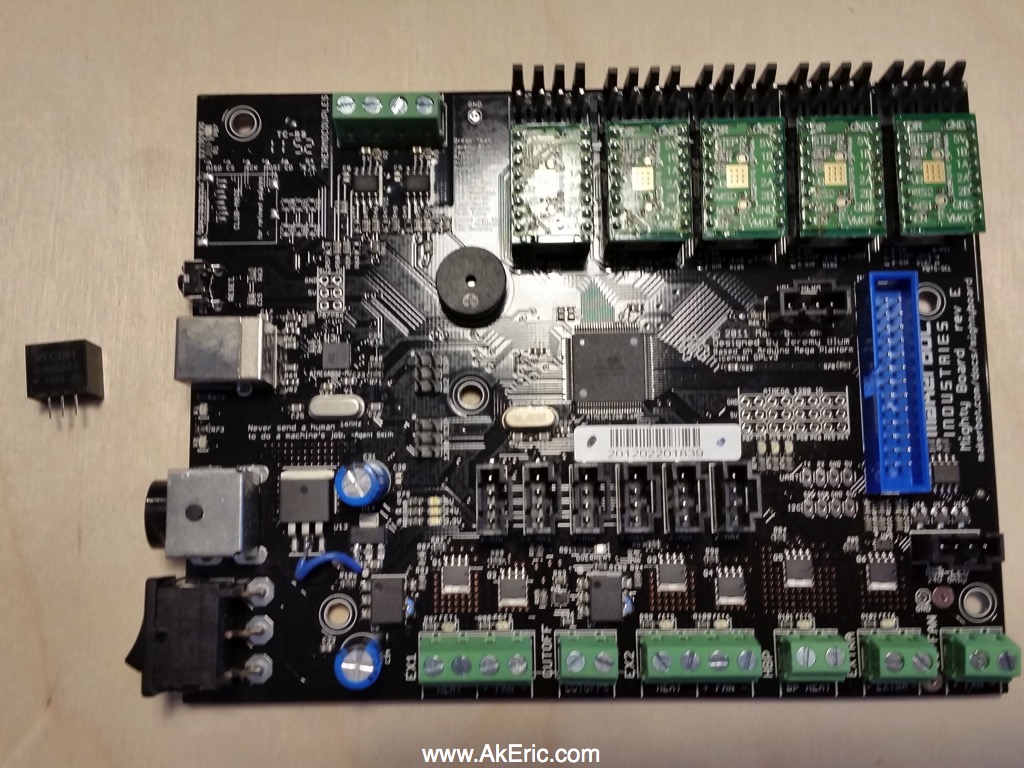
…and removed the board. Here’s a shot of the bare board, and the new voltage regulator:
Like discussed in the forums, I used snips to cut the leads from the old voltage regulator. I then took my soldering iron (the big, red, hand-held kind), and pressing it against the back of the reg, waited for it to desolder from the Mightyboard. I lightly twisted the reg back and forth with a pair of pliers at the same time since I had no idea if just the pressure from the iron would move it. It took a lot longer than I expected, and at one point I thought it wouldn’t work at all. I’m guessing I had to hold it from 5+ minutes.
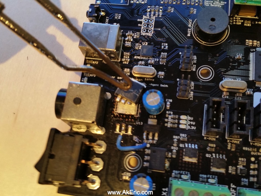
From there I desoldered the old remaining leads, and soldered in the new voltage regulator using wires to aid in the pintout offset. I liked what JetGuy had done in his Flickr post, so I hot-glued it to the power receptacle for extra stability:
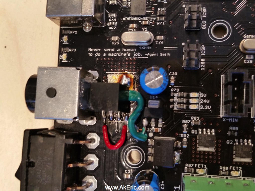 (Note the brown/orange cruft is just left-over flux)
Put it all back together, and I was relieved when it turned on, and printed successfully.
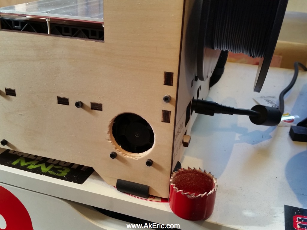
I figured while I had it apart I should provide for some extra cooling, so I drilled out a 1.5″ hole right by the Mightyboard fan. However, after I did this I had more conversation on the above forum linked above, and learned that the Mightyboard really needs no fan cooling at all. But… having it there should’t hurt.
Hope this gives my rep1 many more years of good printing 
My thanks again goes out to the Makerbot Users Google Group users JetGuy, tramalot, and Joseph Chiu for their helpful advice!
Thanks for this tutorial!
The one part that confuses me is the green wire in your final picture. It looks like it is connected somewhere underneath the regulator. What is it connected to on both ends? And why did you remove the blue wire that was there before you made the mod?
Thank you!
The green wire is soldered directly to the large pad on the circuit board itself, which if I remember correctly is ground. One of the legs on the new vreg is also connected to ground, which forms the circuit. I didn’t have to do it that way, but since it’s what I’d seen others do (Jetguy) I figured I’d stick to what works 😉
The blue wire wasn’t needed once the old vreg was removed.
does the clarify things?
@AKeric
Thank you for your reply! I forgot to enable email notifications so I just saw your response.
I received my Voltage Regulator yesterday and want to be absolutely sure what I’m doing before hand! Why is the blue wire in one of your original pictures connected differently than the green wire? Aren’t they supposed to function the same way?
Also: so if the green wire is connected to the ground on one end, what is the other end connected to? I see where it’s connected, but I don’t understand the significance of it. I thought that the red wire is connecting the voltage regulator to the ground?
Thanks a lot for your help!
-Arjun
The legs of the old, and new vregs have different pinouts: i don’t have the data in from of me right now, but what I did was draw a nice pic of the old vreg pinouts, how they connected to the board, and then how the new vreg would connect. Add I mention in the post, the new one had all the pin values shifted one left compared to the old, which was why I needed the wire, since one of the legs didn’t line up with the board properly. But this will vary based on the hardware you picked up: I’d be sure to get the data sheet for it to compare against. I posted links for them above for what I’d picked up. I can’t be more specific than that, only have basic Internet right now 😉
@AKeric
Hmm…I understand that your new VREG was shifted off by one. Your red wire accounts for this shift by connecting the ground leg of the VREG to the ground pin (this is also how JetGuy did it). However, in your pre-modified picture, I don’t see any wire that connects the large pad to the chip that sits below the blue capacitor. But in your picture that shows the modified circuit, the green wire goes from the large pad to that secondary chip (there’s a number “32” written beside it).
That is what is confusing me. I don’t understand what the purpose of that was.
Thanks again for your help!
The green just connects the tiny IC on the right to ground, following how Jetguy had done it. It does what the blue wire used to do, except in the past the blue wire shared a ground pin with the old vreg, since the old vreg was soldered directly to the pad via a tab on its top (that was ground also, and was the part that took me so long to desolder). That wire simply keeps a beefy ground connection.
Oh ok, makes sense. Thank you so much!!!
The new regulator, I ordered the model you listed, do I orient the writing towards the back when I install the new one?
Not sure what you mean by the wiring orientation: Do the images provided not illustrate what needs to be done?
The writing on the new regulator. Does it face backwards in the bottom picture. I just want to make sure
Sorry, I’m just not understanding your question about the ‘wiring being backwards’. If the image doesn’t explain it or the steps I list in the blog, I’m not sure what else I can add 😉 Can you rephrase you question?
I’m not sure which way the regulator is facing, I turned my bot on afterwards and it acts like it going straight to ground. Can you put these regulators on backwards?
I’m honestly not sure. I did it so long ago, the only info I have to go off of is my own blog pics. You should ping the Makerbot Users google groups for more info, they can probably help you more than I can at this point:
https://groups.google.com/forum/?fromgroups#!forum/makerbot-users
It’s definitely words facing you. I found out the hard way
So I changed my voltage regulator with a 5 volt regulator but the screen doesn’t turn on. Only the stepper motor driver LEDs turn on. What should I do?
I don’t have a good answer for you, since I’ve only done this operation once, and it worked.
I’d post your question here:
https://groups.google.com/forum/?fromgroups#!forum/makerbot-users
There are a lot of people far more knowledgeable in Replicator electronics than I am.