Jump to C-Bot blog index to see all the posts.
This post can also be prefixed “Building the C-Bot 3D printer part 34:”
Overview
This post covers the steps I went through getting RepRap Firmware (RRF) installed on my C-Bot’s RADDS/Due combo. My goal is to lay out all the steps & pitfalls I went though to get it working, in detail, since I could find no page online that already illustrated this. Even though I’ve used several other firmwares in the past there were may concepts that were new to me (and probably not new to those more experienced in programming), that I’ll hopefully illuminate to others that were as much in the dark as I was.
It is mainly about RRF, and not the RADDS hardware itself: That is covered in depth by my C-Bot’s ‘Upgrade to Repetier‘ post, no need to dupe all that here.
Note, written in hindsight: Had the “Duet Wifi” (or Ethernet) been available at the time I’d done this hardware upgrade, I would have gone that route. If you’re considering this firmware as an option, I’d highly encourage you to go that route. The hardware is more expensive, but you’re no longer dealing with a firmware port.
For some context of my experience (and I’m not saying my experience is ‘high’, more of a squishy-medium), previous firmware/hardware combo’s I’ve used/installed/tweaked include:
- Sailfish/Mightyboard on my Makerbot Replicator 1
- Marlin/Rumba on my C-Bot
- Repetier/RADDS on my C-Bot
Why do this?
I had two main goals for installing RRF on my C-Bot:
- See if these weird vertical lines that were showing up on my prints when I switched to Repetier/RADDS would go away (and also to check out it’s overall comparative performance differences): I figured this had something to do with Repetier & CoreXY printers. As it turns out, it does not: The same lines still show up in RRF :S You can see pics of that issue in this Repetier Forum Post.
- Does firmware designed for 32 bit hardware have a leg up on firmware (Repetier) ported to 32 bit hardware? The jury is still out, but my initial impressions (now that I’ve been using it for a few weeks) are positive.
Resource Link collection by webpage
- dokku.radds.org
- Duet3d.com
- Duet Wifi Wiki Link – This is for the newer Duet Wifi hardware that came out after I authored this post, but there’s a bunch of great info in there.
- Forum : For both the Duet Boards, and RepRap Firmware.
- Filastruder
- US Distributor for the ‘Panel Due’ link.
- Makerfarm:
- US Reseller of RADDS hardware, link.
- RepRap Forum:
- RepRapWiki : Info
- reprapfirmware.org:
- GitHub :
- RepRap Firmware:
- RepRapFirmware/Release/RADDS – Update: Looks like DC42 is now updating RADDS, which is great. This starts with v1.17a
- Old distributions:
- dcnewman/RepRapFirmware-RADDS – (old) Main github repository for RRF & Due/RADDS. This is what you want for version 1.09 & 1.10
- dcnewman/RepRapFirmware Release folder: – While this isn’t the RADDS github below, Dan started posting newer versions in here. As of this authoring 1.13 and 1.14 are in there. Be sure you download the ‘RADDS’ versions.
- Release versions here.
- RADDS Hardware:
- RADDS 1.5 install binary docs here. <- This is the most helpful page I found to set it up.
- RADDS 1.5 build from source docs here.
- Also need dcnewman/CoreNG to build from source, if you’re doing that.
- Also note that dcnewman has a non-RADDS RepRapFirmware github repository. Do not use that one (that I mistakenly started with), it’s for the Duet(?). Basically, if you’re using a pre-compiled binary (.bin) file, make sure it has ‘radds’ in the name.
Notes on RRF & it’s history
Big Thanks
Goes out to Dan Newman for his patience & tireless forum replies helping to guide me through this, plus other forum posters David Croker\dc42 (who helped write the dc42 fork of RRF) and GroupB.
My build environment
Hardware
- All of this work was done on an ancient Macbook Air running OSX Yosemite 10.10.5.
- RADDS 1.5
- Arduino Due R3 (Note, that version of the Due has a ‘reset bug’, described below under ‘Issues’. You want a Due R3-E to avoid this issue).
Software
- Mentioned below, I installed the older Arduino 1.5.8 to get access to Bossac.
- I do my text editing in Sublime Text 2.
Build from source
Docs: https://github.com/dcnewman/RepRapFirmware-RADDS/blob/master/INSTALL.md
Note #1: I did not do this (build from source). Nor do you actually need to, but since I did so much work not knowing this, I listed it below.
Note #2 : You mostly like will still want to clone the git repository, shown below.
Scons is required to build from source, and I had a nighmarish time getting it installed, and around that time in the fourm posts someone said “why not just install a prebuilt binary” using bossac?. Which I didn’t know how to do either  The key piece of knowledge from that was:
SCONS : Builds the source into a .bin
BOSSAC : Upload compiled .bin to the Due
For what it’s worth, here’s my notes for ‘building from source’:
Get the git repository
You’ll want this anyway even if you’re not building from source, since it has the precompiled binaries, plus example macros required later.
On my Mac, I have my git root set to:
~/git
This is my original install location:
$ git clone https://github.com/dcnewman/RepRapFirmware-RADDS.git
So it installs here:
~/git/RepRapFirmware-RADDS
But since authoring this, DC42 has taken over, so instead you’ll want:
$ git clone https://github.com/dc42/RepRapFirmware.git
Which includes the RADDS builds.
Scons:
I could only get scons installed by doing a MacPort. And again, you only need to do this if you want to build from source.
$ port install scons
And then spending an hour getting various packages updated. It was a nightmare.
Get bossac & configure Arduino IDE
Mac
To get bossac (which you need to later flash the compiled .bin to the Due) for the Mac, you need an older cut of Arduino, 1.5.8: I can’t seem to find bossac anywhere on my Mac based on the latest release.
https://www.arduino.cc/en/Main/OldSoftwareReleases#1.5.x
This is where you can find bossac on a Mac (note how I changed the Arduino App name so as to not clash with the more current install I also have):
/Applications/Development/Arduino_158.app/Contents/Resources/Java/hardware/tools/bossac
PC
bossac.exe seems to come packaged with the latest Arduino IDE:
C:\Users\<USERNAME>\AppData\Local\Arduino15\packages\arduino\tools\bossac\1.6.1-arduino\bossac.exe
Also, dc42 provides a download for it here:
https://github.com/dc42/RepRapFirmware/tree/dev/Tools/Windows
Configure the IDE
Since I’d already done it back when I installed Repetier, I’m not sure how important this next step is. But if you run into problems: You may need to ‘install’ the Due board in the Arduino IDE: The bare bones instal doesn’t know anything about the Due. Check out my post here under ‘Configuring the Arduino Due with the Arduino IDE’ on how to do this.
I didn’t get any further, since at this point I realized I didn’t need to build from source at all…
Flash precompiled binary / manual firmware update
Docs: https://github.com/dcnewman/RepRapFirmware-RADDS/blob/master/doc/RADDS-v1.5.md
Update: If you’re using 1.18.1 or newer (the docs say 1.13 or newer, but it didn’t work for me until 1.18.1), you can use the auto-update function instead of this method. See that section at the bottom.
You need bossac to flash a precompiled bin to the Due. If you haven’t already get bossac installed, see the previous section for that.
BOSSA is an acronym for Basic Open Source SAM-BA Application. Not sure what the ‘C’ is for…
There is a Mac standalone app for this, but it’s known to not work with RADDS, so spare yourself the trouble.
Issues
I had a number of problems trying to flash the bin:
- The Due has two programming ports, the ‘Native port’ (furthest from the barrel-jack) and the ‘Programming port’ (closest to the barrel jack).
- You’re supposed to be able to flash the bin over the Programming port, only having to press the (easily accessable) reset button. I could not get it to work.
- The only other alternative is to use the Native port, but to do that, you have to first press the Due’s erase button, then reset. Issue is, the erase button is completely hidden by the RADDS shield. So I had to unwire everything from the board to get it out of the case, pry the RADDS shield off the Due, and do the erase\reset\native port combo. But, it worked.
- It appears this “can’t use programming port” may stem from a firmware issue on the chip that drives the Due’s USB (discussed at the bottom under “issues”). Basically, whenever you power on the Due, you must also press reset before you can connect to it.
You need to know what USB port the Due is on. The easiest way I found this was: Power it on. Press reset to get around bug. In either the Arduino IDE, or in Simplify3D (the slicer I use), see what’s listed to connect to.
You also need to know which binary to install. There are multiple ones available in the /git/RepRapFirmware-RADDS/Release/ folder: I started with RepRapFirmware-1.09r-dc42-radds-b.bin, being told that was the most tested and stable at this point. I quickly later upgraded to RepRapFirmware-1.13a-radds.bin, which has the advantage of allowing future firward upgrades to occur directly off the SD card. See the notes here, and here.
Process
Based on the above bossac install dir, this is what I used to flash the bin to the Due:
- Connect USB to native port on the Due.
- Press erase on the Due. I waited 5 seconds (not sure how long to wait but that worked). Note if the RADDS shield is on the board and the erase button is hard to access, you can use a popsicle stick cut in half to reach it, with the help of a flashlight and extra pair of hands.
- Press reset on the Due. Again waited 5 seconds (not sure how long to wait but that worked).
- Ran the below command: The shell showed me the progress, with a successfully completion.
$ /Applications/Development/Arduino_158.app/Contents/Resources/Java/hardware/tools/bossac --port=tty.usbmodem2621 -e -w -v -U true -b /Users/<USERNAME>/git/RepRapFirmware-RADDS/Release/RepRapFirmware-1.13a-radds.bin
The short version (without paths) for readability is:
$ bossac --port=tty.usbmodem2621 -e -w -v -U true -b RepRapFirmware-1.13a-radds.bin
Note if you can get the programming port to work, you need to set ‘-U false’.
If performed successfully, you should see something like this:
Erase flash
Write 195708 bytes to flash
[==============================] 100% (765/765 pages)
Verify 195708 bytes of flash
[==============================] 100% (765/765 pages)
Verify successful
Set boot flash true
Test initial connection
Once you’re flashed the bin, how do you know the firmware is actually working before moving foward? These steps will let you know it’ safe to continue. You can do this even before the RADDS is plugged into the Due.
Reminder: Connect the USB cable in in Native USB port (the one furthest from the barrel jack) of the Due, then to your computer (order doesn’t matter).
The Due ‘reset’ bug
Note, it appears that my Due has a bug with the chip that drives the USB firmware : Because of this, after I power it on, I must press the reset button (on the Due or RADDS) for the firmware to actually load. I had this same issue using Repetier. If you don’t press the reset button after it turns on, your computer may not be able to communicate over USB correctly, and you’ll spend hours searching the internet like me trying to figure out why. This is discussed in more details in the “Issues” section at the bottom.
Three different methods I used to connect to the machine, immediately after flash. I’ve listed the USB ports that I used below, yours will most likely be different.
Connect via Simplify3D
- Press reset on the RADDS board.
- Via S3d ‘Machine Control Panel’, connect at 115200 baud to USB port /dev/cu.usbmodem2621 (on my Mac) or COM5 (on my PC)
- See the section below for actually configuring Simplify3D for printing with RRF.
Connect via Arduino
- Press reset on the RADDS board.
- Tools -> Board -> Arduino Due ( Native USB Port)
- Port -> /dev/cu.usbmodem2621 (on my Mac) or COM5 (on my PC) : Arduino Due (Native USB Port)
- Open the Serial Monitor. Set baud to 115200.
- Make sure that “Newline” is set in the field to the left of the baud rate: Fresh installs can have ‘No line ending’ set, which doesn’t work well…
- Note that if the text “( Native USB Port)” doesn’t show up in the lists, the board isn’t connected properly, or the Due wasn’t configured properly.
Connect via Octoprint
- It should be noted that as of Feb 2017, it’s possible the latest version of Octoprint auto-detects RRF now. However, if you have issue, these older notes may help:
- Based on this forum post, need this plugin in Octoprint to make it compatible with RRF:
- https://github.com/markwal/OctoPrint-RepRapPro
- Just browse the Octoprint plugin manager to this file to install:
- https://github.com/markwal/OctoPrint-RepRapPro/archive/master.zip
- To connect, press reset on the RADDS board, choose the serial port ‘/dev/ttyACM0’ (for the RPi) and ‘Connect’.
- If no serial port shows up after pressing reset on the RADDS, reload the Octoprint page.
- See the section below for actually configuring Octoprint for printing with RRF.
To test the connection
Enter M115 into your serial console to report config status and know it’s actually working: If the SD is in there with a /sys/config.g file (more info on that below), it should print something similar to what I have below, otherwise it’ll report ‘no config file’ (which still means things are working).
Send: M115
Recv: FIRMWARE_NAME: RepRapFirmware FIRMWARE_VERSION: 1.09r-dc42 ELECTRONICS: RADDS 1.5 DATE: 16/02/27
Then I plugged the RADDS back on top of the Due, and hooked up all the wires (more on hardware hookup below).
Macro Config
Update: Since I’ve written this blog, a new “RRF Configuration Tool” is out in the wild: Seems very similar to how Repetier does it (and that’s a good thing). I’ve not yet used this configurator myself, but it may be a good starting point.
Macro files are the way you configure RRF. They are .g text files that live in the /sys folder on the RADDS SD card, and allow RRF to reconfigure itself every time you turn it on: No longer do you have to recompile the source to make an adjustment: Just tweak the file on the card and reboot.
To get started, copy the content of /git/RepRapFirmware-RAADS/SD-Image/sys-CoreXY (presuming you’ure using a CoreXY machine like me) to your sd card root, and rename it to /sys
From there you can start editing the file: Each time you plug it back into the RADDS board and reboot (and press reset after…) the config will be in play.
Good overview post on initial config: http://blog.think3dprint3d.com/2015/02/reprapfirmware-config-files.html
Good overview of macros in general: http://reprap.org/wiki/RepRap_Firmware_macros
The Wiki lists defaults for many Mcodes here. I’ve experienced these defaults to in fact be incorrect in some instances: If you plan on using a default, be sure to enter that Mcode into a serial monitor to see what it returns, and is valid.
Primary macros I use are as follows:
config.g
config.g is the main macro that is executed when the machine is powered on. It’s akin to Configuration.h in Marlin & Repetier. Below are the main steps I went through getting it configured, and describing what the M & G codes do… mainly for my own sanity as I learn this.
Set CoreXY Mode
Per http://reprap.org/wiki/Configuring_RepRapFirmware_for_a_CoreXY_printer, presuming your bot is CoreXY:
M667 S1 ; set CoreXY mode
Setting max feed rates
Via M203
The wiki lists default values for M203 to be the values I list below. However, before I set that, when I’d enter a M203, they’d actually come out to 6000 (mm/min) for XYZ: Substantially slower than what I put in: This was clipping my speeds going much past 100mm/sec. Values below freed things up.
My Values:
M203 X25000 Y25000 Z25000 E8000 ;
Defining nozzle and bed thermistor
Via M305
I’m using a E3d-V6 thermistor for my Volcano hotend.
They state:
RepRapFirmware
Use the Beta value 4267K.
It’s 100k Ohm
M305 P T B R L H X
- P : Heater Number : Not to be confused with the ‘P’ (tool) value of M563. 0 = heated bed (RADDS bed), 1 = first extruder (RADDS H0). 2 = second extruder (RADDS H1), 3 = third extruder (RADDS H2).
- T : Thermistor resistance at 25c
- B : Beta Value
- R : Series Resistor Value
When communicating with the RADDS, if you enter a M305 P0, it’ll print the current state.
My Values (just a generic 100k one for the bed), RADDS has a 4700 ohm inline resistor.
M305 P0 T100000 R4700       ; P0 = Heater 0 = The bed.  Not sure the 'beta' value for this.
M305 P1 T100000 R4700 B4267 ; P1 = Heater 1 = The extruder nozzle. Beta per the E3D docs.
Note, you’ll know these values are wrong if at room temp (25C / 77F) your control software (like Simplify 3D) doesn’t read 25(ish)c : I had originally set R1000, and it reported the resting temp to be 60c, very, very wrong.
Note I’m using the default PID settings for both nozzle and bed, and they seem to be working just fine.
Defining ‘Tools’
Via M563
This is where you setup your hotend(s).
M563 P D H
- P : Specifies the ‘tool‘ number, 0 -> infinity.
- D : The drive(s) used by the tool : 0, 2, 3 : D0 <-(zero) Is the first drive after the XYZ steppers, so presumably the extruder stepper.
- H : The heater(s) used by the tool : 0, 1, 3 : 0 = Heated bed, 1 = first extruder heater.
My Values:
M563 P0 D0 H1 ; Tool (P) 0 : D0 = Extruder stepper 1. H1 = First extruder heater.
To select a tool in gcode, use T# to select it, T99 to deselect (needed?)
Defining axis direction and enable values
Via M569
M569 P S R X Y Z E
- P : Specifics the ‘drive‘ number, not to be confused with the ‘P’ (tool) value of M563. 0=X, 1=Y, 2=Z, 3=E (right?).
- S : Whether the drive should move forward. 1 = forward, 0 = backward.
- R : Logic level. 0 is Default. Set to 1 to reverse logic if you’re using RAPS128.
My Values:
M569 P0 S1 ;  X
M569 P1 S0 ;  Y - I needed to reverse this.
M569 P2 S1 ;  Z
M569 P3 S1 ;  E1
Set Endstop configuration
Via M574
M574 X Y Z S
- X, Y, Z : The switch type for the axis : 0 = none, 1 = low (min) 2 = high (max).
- S : Logic level : Defines whether the endstop input is ‘active high’ (S1, the default), or low (S0).
My Values:
M574 X1 Y1 Z1 S0
You can use M119 to report the status of your endstops. Makes it convenient to test them while holding them on. I had a super nasty bug where my X endstop wasn’t seated properly in the RADDS board, so it always reported off.
Defining steps per mm
via M92
For all steppers, X,Y,Z & E
My Values, copied from Repetier (with X&Y divided by 2, since Repetier doubles the XY steps for core-xy machines), since I’m using the same SD6128 drivers at 1/32 microstepping.
M92 X199.743 Y200.542 Z804.91
M92 E325
Fans
They were an amazing pain: I have a hotend cooling fan, and a PLA cooling fan. I also have a case cooling fan I never could get working via the below config, so I just hooked it up directly to my power-supply so it’s always on (Repetier was able to control it, so +1 for it).
This is what finally worked:
M106 P0 T60 H1 ; Hotend cooling fan: Enable to auto kick on at 60c (make it 'thermostatic').
M106 P1 H-1    ; Filament cooling fan: Must do H-1, or it'll turn on with P0 for some reason.
M106 P1 S0     ; Filament cooling fan: Must do, or it will go full blast on start :S
Comments:
- If I didn’t declare P1 (filament cooler) non-thermostatic (H-1) it would turn on with P0 (hotend cooler).
- If I didn’t set P1 (filament cooler) to a speed of 0, it would go full blast on machine start.
- Still haven’t figured out how to hijack pin H2 to double as a case cooling fan (see complaint above).
Stuff to comment out / delete
From the default config.g:
- All M540, M552, M553, and M554 (network) commands, not supported by RADDS.
- M906 (motor current) commands : Not supported by RADDS.
Setting up extruder and bed PID
I wasn’t aware of this info at the time of my initial build, but there’s a great overview here on how to configure the PID on both your extruder, and heated bed here:
https://duet3d.com/wiki/Tuning_the_heater_temperature_control
Note that with RRF v1.15, there’s a PID autotune feature that can be used. As of this authoring though, only 1.14 has been ported to RADDS 
I will also note that the default PID tuning for the hotend has been working fine, and my heated bed has been on a bang/bang relay (also the firmware default).
Related MCodes (RRF v1.09 and newer):
- M301 : Set PID for hotend.
- M304 : Set PID for bed
And if you have RRF 1.15 or newer:
homeall.g
This macro is called to during a ‘home all’ G28 operation
+ homex.g, homey.g, homez.g are just like it, but only on those individual axes.
Per http://reprap.org/wiki/Configuring_RepRapFirmware_for_a_CoreXY_printer
Make sure you set the G1 commands when moving the head some amount past your build volume, so they’ll be sure to hit the end-switches no matter what. For example, my X platform width is 305mm. So when homing:
G1 X-330 F3000 S1
I set it to go -330, just to make sure it hits.
bed.g
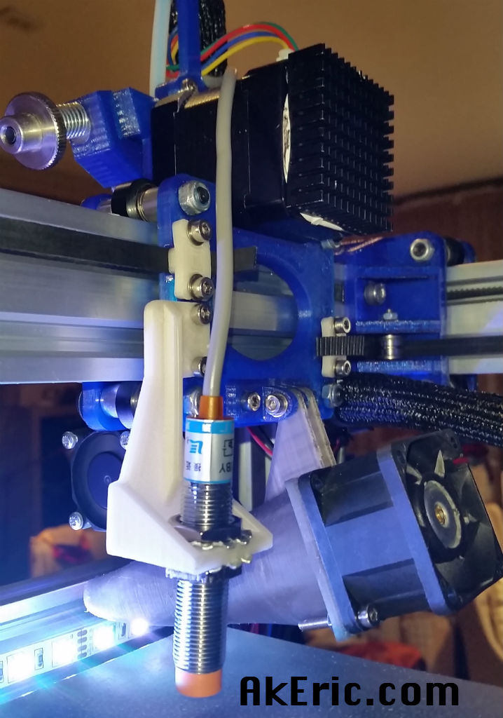
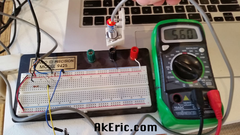
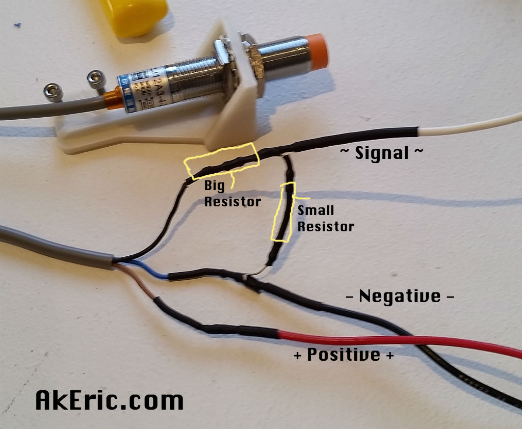
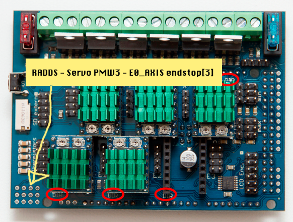
If you want to use an inductive probe to help level you bed, you do all that magic in bed.g (or optionally in config.g with M557 commands). I hadn’t set that up at the time of this post, but I did later: Find a robust post here on setting up an inductive Z-probe: http://www.akeric.com/blog/?p=4062
Macro M & G code usage
Macros can live in the /sys folder, or in the /macros directory with any extension.
While in a macro, you can call another macro. Macros are searched in /sys directory and it is recommended to always specify explicitly the path.
M98 calls to other macros.
When are Macros called to?
- config.g : Machine starting up
- Pausing & Resuming:
- resume.g : M24 (Start/Resume SD Print)
- pause.g :
- M25 – (Pause SD print) – From control panel\lcd\serial connection, not saved gcode.
- M226 – (Pause SD print) – From gcode directly.
- cancel.g : If a M25 is executed pausing a print, then you execute a M0, this is called to.
- stop.g : Docs say this is called while M0 is executed, (or?) when a paused print is cancelled. NOTE: Mine doesn’t seem to execute at all though via a M0, paused or not. I have no idea how to trigger this.
- Homing:
- homeall.g : G28 (Move to origin: Home)
- homex.g, homey.g, homez.g : Called to for individual axes on G28.
- bed.g : G32 (Probe Z and calculate Z plane) – If using auto leveling. See my post here.
- Tool selection:
- tpre0.g : Before tool1 is selected
- tpost0.g : After tool1 is selected
- tfree0.g : When tool1 is freed
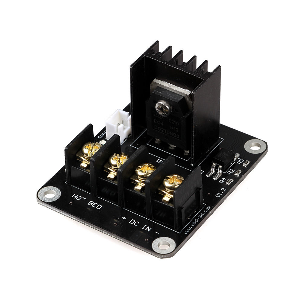
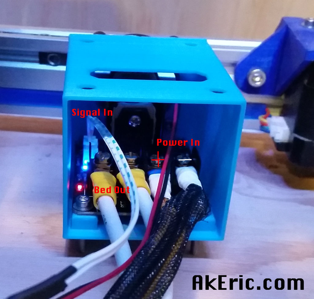
Wiring the hardware
I cover how to hook up hardware to the RADDS in depth in ‘this post‘, scroll down to the ‘Connecting the hardware’ section.
Some notes from this doc, for the RADDS board:
- The minimum endstop headers are used for the endstops: X min, Y min, and Z min.
- Thermistor position T4 is used for the heated bed. This is the thermistor header farthest from the board’s corner.
- Thermistor position T0 is used for the first extruder, T1 for the second, etc.
- Controlling fans:
- Fan0 with ‘M106 S# P0′. Where S is 0-255 . P0 is default, and can be omitted. This if the hotend cooler.
- Fan1 with ‘M106 S# P1′ : This is the PLA cooler on the hotend.
Configuring to print with RRF
If printing over SD, RRF expects your .gcode files to live in a /gcodes folder on the SD.
Print off the SD via MCodes & a serial connection
You can print via a serial connection by directly issuing M-codes:
M20                ; list sd card contents to see what's there
M23 myPrint.gcode  ; select the gcode to print by name
M24                ; start the print
Configuring Simplify 3D
- In the ‘Firmware Configuration‘s’ FFF tab:
- To tell it to control the second fan (PLA cooling fan) not the first fan (hotend cooler).
- Set Fan Power: M106 S$ P1
- Set Fan Off : M106 S0 P1
- RRF uses M116 to stabilize temps (I’m told M190 & M109 are deprecated).
- Stabilize Extruder Temp: M116
- Stabilize Bed Temperature : M116
- Note, you loose all serial communication while these are in use: Including temp readings, so you’re a bit blind during that time if you have this setup to do so in your ‘start script’.
- In the ‘Firmware Configuration‘s’ Communication tab:
- Make sure that “Allow Command Buffering” is checked, and set the “Serial Cache Size” to 127 bytes: When I had the default (63) set, I was unable to print over USB, it would lock the machine about half way though my ‘start script’, right after a G28 (home) operation.
- Note, to print consecutively over USB, I have to reset the printer, and reconnect after each print, or it will lock up like mentioned above. This is different behavior than Marlin/Repetier.
- In the ‘Firmware Configuration’s‘ Macros tab:
- S3D’s default “Extrude/Retract” buttons in the Machine Control Panel don’t seem to behave correctly: They want to extrude based on “absolute values”, not “relative” ones. The side effect is during a paused print, if you extrude 10mm, you can’t extrude any more unless you retract 10mm first. To get around this, if you execute a M83 first, it’ll put the extruder in relative moves, and you can extrude as much as you want.
- I make a Macro called “Relative Extruder Moves” and put a M83 in there. I press that before I do any type of control panel extrusion.
- Note you have to “Export” your firmware settings to get it to save. The ‘save’ button doesn’t actually seem to save anything.
- In a given Process:
- Temperature Tab:
- For all extruder and bed temp controllers, uncheck “Wait for temperature controller to stabilize before beginning build”.
- You ask “Why? This is a great feature”. Indeed it is, and I agree.
- However, while the temp stabilizes via M116, you’ll get no serial communication back from the board, making you both blind to what’s happening, and unable to communicate with it in any way, to (for example) stop it if needed.
- You’ll need to pre-heat the machine and get it to temp before starting your print if you go this route.
Configuring Octoprint
- Update 2: As of Feb 2017, it’s possible that Octoprint will auto-detect RRF, and the below plugins aren’t needed. I’ve note tested this myself though.
- Update 1: As of Octoprint v1.2.15, RepRapFirmware is now supported! You still need to install the RepRapPro plugin, and update the “Settings->Features” section to “Select SD Files by relative path” & “Always assume SD card is present”, but otherwise it works!
Old notes below, before RRF was fully supported by Octoprint:
- As of this authoring, the main branch of OP isn’t designed to work well with the RADDS SD card: Doesn’t recognize it properly, so you can’t print off of it. You can print off the Octop’s SD via USB however. I’m not a fan of printing over USB, so I didn’t like this option.
- Thanks to work by Mark Walker while I dealing with all this, he updated a dev branch of OP to recognize the SD card, making it possible to print from it like any other firmware. To get this dev branch, follow the directions below. It worked for me without a hitch. Thanks Mark!
- In the Octoprint’s settings, under ‘features’:
- Check ‘Enable SD Support’
- Check ‘Always assume SD card is present’,
- …or you won’t be able to see the SD card on the RADDS.
- Once you’re on the dev branch (below), also check ‘Select SD files by relative path’ to be able to print off the SD correclty.
- Also don’t forget to install this OP plugin: https://github.com/markwal/OctoPrint-RepRapPro/archive/master.zip
- Finally, once you’ve switched to the dev branch, do not update Octoprint: It will overwrite the update, and you’re back to square one. Hopefully they’ll roll these updates into mainline at some point.
Switch Octopi to the dev branch (again, no longer needed post 1.2.15) that supports printing off the SD card on RRF \ RADDS:
This is a condensed / modified version of this Octoprint FAQ. Like they explain, only use sudo on the FIRST COMMAND listed below, and nowhere else.
SSH into your pi. Then:
sudo chown -R pi.pi ~/oprint ~/OctoPrint
cd ~/OctoPrint
git pull && git checkout dev/rrpFileOpened
~/oprint/bin/python setup.py clean
~/oprint/bin/python setup.py install
sudo service octoprint restart
When Octoprint restarts, you should see this version at the bottom of the web interface:
1.3.0.dev784+gf8c67fd (dev/rrpFileOpened branch)
Updating the firmware
(According to the RRF docs) If you’re running v1.13 or newer, you no longer have to do the ‘press the Due reset button’ dance. Instead, you can follow the process Dan Newman outline here, or follow the steps below (copied & modified from that page):
- Power down the RADDS board and remove the SD card.
- Download the latest RADDS compiled .bin file from:
- https://github.com/dc42/RepRapFirmware/tree/dev/Release/RADDS/Edge
- Rename this file to “RepRapFirmware-RADDS.bin”, and copy it to the “/sys” folder on the DS card.
- As an aside, if you were doing this for a normal Duet, the name would be “RepRapFirmware.bin”
- Also, download and place the below file in the SD card’s sys/ folder.
- https://github.com/dc42/RepRapFirmware/blob/dev/Release/RADDS/Edge/iapradds.bin
- If there already was an iap.bin in there, remove it.
- Eject the SD card and place it back into the RADDS.
- Connect to the RADDS over USB (or from a Panel Due) and send the command M997 S0.
- Important: I was unable to get this to work using Simplify3D’s serial monitor, since S3D constantly pings the board for the temp. This caused the update to fail. I was able to successfully get this to work via the Ardiuno IDE’s Serial Monitor.
- Wait about a minute and then reconnect to the RADDS board. The new firmware should be installed. The RepRapFirmware.bin file is removed from the SD card automatically.
- You’ll probably have to reconnect to the board via the Arduino serial monitor, but if you execute a M115, the new version info should be displayed.
- Note: When you do this with a RADDS board connected to peripherals (e.g., stepper motors), it is recommended to do this with the bot’s power on. Particularly if you have RAPS128 drivers which may, owing to their inverted enable, turn on during the upgrade and when the processor is running under the iapradds.bin firmware. Peripherals may draw more power than a computer’s USB port will provide (typically a max of 500mA).
Update:
Up until versions 1.18.1, I was unable to get this process to work. It “just wouldn’t”, and I’ve have to manually update the firmware by pressing the on-board reset button via a broken-in-half Popsicle stick. But when upgrading from 1.18.1 to 1.19.2, it magically started working. So much easier now!
Issues
Outstanding:
Resolved:
- Can’t update Firmware via “M997 S0” : See notes directly above.
- Solved: Up until 1.18.1, this didn’t work. But, when I upgraded from 1.18.1 to 1.19.2, it started working. Finally!
- M190 (Heat bed and wait for target temp) & M109 (heat hotend and wait for target temp) cause machine to loose communication during heatup.
- The commands tell the machine to ‘do nothing until target temp is reached’. This includes any serial communication in RRF (compared to Marlin\Sailfish\Repetier that keep the serial communication lines open in my experience). The side effect is the appearance that you’ve lost USB connection: Communication will come back when target temp is reached, but in the meantime you’re blind. I don’t like it.
- I’m told that M190 & M109 are deprecated in RRF, and to use M116 instead: While this command works, it still also hangs all communication in the process as well.
- Solved: Don’t use any of those Mcodes, and just heat everything up before hand manually. I don’t like this, but it works.
- Endstops not being detected no matter what combo of values is entered into M574.
- Solved : X-endstop wasn’t seating correctly in the RADDS.
- PLA Cooler fan turns on automatically when using M563 to define the first tool.
- Solved : Setting Fan0 to thermostatic (turn on when hotend reaches certain temp) it aut0-fixed this. Weird.
- PLA Cooler fan doesn’t respect PWM control: It’s either 100% on, or off.
- Solved: Needed tricky config.g, see above.
- Extruder doesn’t seem to be reading the correct temperature.
- Solved: Wrong inline-resistor value: had 1000, should be 4700 (what’s on the RADDS boar).
- RADDS case cooling fan is hooked to H2 (hotend heater2) in Repetier successfully : How to configure that as a fan in RRF? Still haven’t figured it out yet.
- In the meantime I rewired them to mains so they kick on automatically when the machine is powered on.
- The Due reset bug: Whenever I power on the Due\RADDS, I have to press reset to actually make it boot the firmware. This happens in Repetier too.
- Described here as well: http://forums.reprap.org/read.php?13,569468,579517#msg-579517
- Appears to be a bug in the firmware of a chip on the Due itself:
- From above post : “all Arduino due R3 have this problem and there is an new version called R3-E that do not have the problem”.
- So if you’re going to buy a new Due, make sure it’s an R3-E!
- RADDS LCD is not supported at this time, but the PanelDue is. Plus, it’s a touchscreen.
Jump to C-Bot blog index to see all the posts.